
Introduction
Have you ever wondered how data is sent through the network from one machine to another? If yes, then the Open System Interconnected model is what you are looking for.
The OSI model is used to help standardize and characterize how data should flow from sender to receiver without taking into consideration the underlying internal structure of the endpoint (sender, receiver).
The organisation that came up with this model is the International Standardisation Organisation and hence this model is formally referred to as ISO - OSI.
Architecture
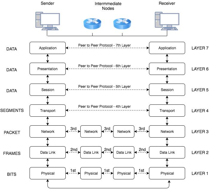
As in the figure below the model divides the network into 7 layers. Data communication in the OSI model starts with the top layer ( Application Layer ) of the stack at the sending side, travels down the stack to the sender’s lowest layer ( Physical Layer ), then traverses the physical network connection to the bottom layer on the receiving side, and up its OSI model stack.
We go for a layered approach because it is easy to design independent layers with dedicated functions which interact with each other as compared to a single complex model.
Important Observations
- End-to-end layers: In the diagram above, you would notice that the upper layers of the protocol (Application - Transport), the sender’s and receiver’s layers are directly connected via arrows. This is because these layers are not aware of intermediate devices that are used to transport data (such as switches and routers). These layers appear to communicate directly with each other.
- Unit of Data: In the diagram above, to the extreme left is the unit of data that is used in each of the layer. The transport layer (and the layers below it) have a unique name for the unit of data being transferred from sender to receiver.
Functions of Layers
- Layer 1 - Physical Layer: The physical layer is the lowest of the OSI Layers and the most complex. This is because of the underlying hardware technologies used. The function of this layer is to define how the bit stream will be transmitted rather than the logical data packet. It deals with defining which frequency will the bit be transmitted on, what kind of modulation will be used, how the bits will be grouped and other low lying physical parameters needed for transmission of bits.
- Layer 2 - Data Link Layer: The data link layer is responsible for transferring data to adjacent devices on the same Local Area Network (LAN). This layer also has provisions to make sure that error-free data is being passed on to the higher layers from the physical layer. Hence, it contains error detection and correction mechanisms to ensure the integrity of data is maintained.
- Layer 3 - Network Layer: The network layer is responsible for forwarding packets to other networks. Usually a network is divided into multiple subnets and the network layer with the help of routers forwards packets between such networks to establish a Wide Area Network (WAN).
- Layer 4 - Transport Layer: The transport layer ensures that messages are delivered error-free, in sequence, and with no losses or duplication. It relieves the higher layer protocols from any concern with the transfer of data between them and their peers.
- Layer 5 - Session Layer: The session layer allows session establishment between processes running on different stations.
- Layer 6 - Presentation Layer: The presentation layer formats the data to be presented to the application layer.
- Layer 7 - Application Layer: The application layer serves as the window for users and application processes to access network services.