By Taron Foxworth
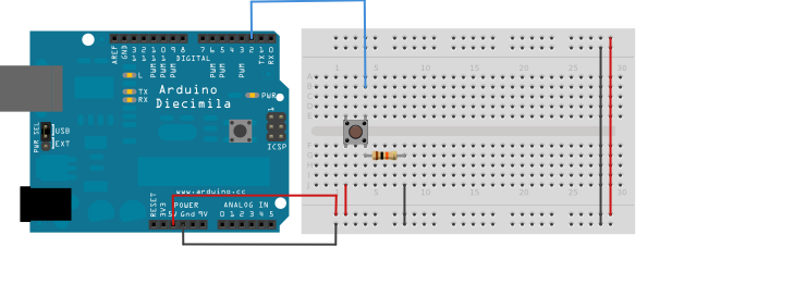
If you’ve ever wired up a button to an Arduino, you’ve come across this diagram:
At first, this can be confusing. My first thoughts: “Why do I need a resistor? I just want to it to tell me whether the button is being pressed.”
After a lot of reading, there wasn’t a simple explanation.
What’s going on here
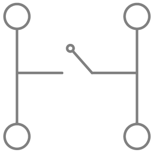
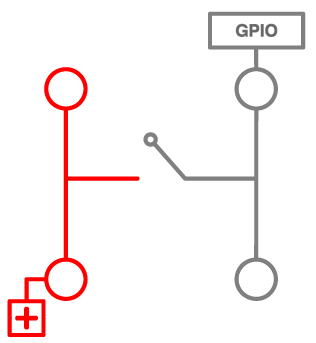
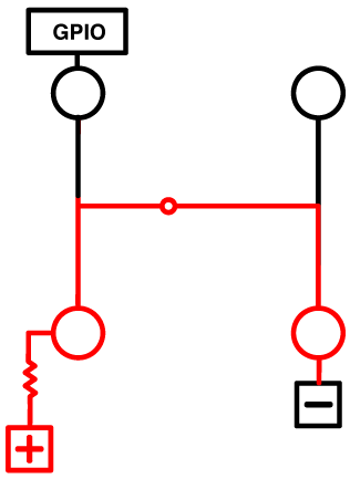
In that button — AKA a switch—the wires are shaped in the form of an “H”. But the middle isn’t connected — or the circuit isn’t connected — until we press the button.
In reality, we want to read from the Arduino a 0 when nothing is connected and a 1 when the button is pressed.
On the Arduino, this is called General Purpose Input Output (GPIO).
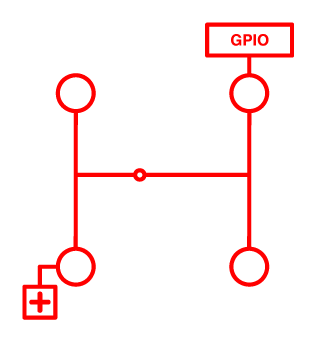
So, we can do something like this:

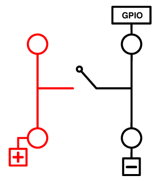
We connect positive (5v, 3.3V, or VCC) to the left side of the circuit.
Now, when the button is pressed, the GPIO will read a 1, and all is good.
Well, no. Let’s take a look at Diagram 2 again:
We wanted a 0 when nothing is connected, but how can you guarantee this? Currently, there is no way to guarantee the GPIO to be 0.
There is also electromagnetic frequencies in the air that could draw your GPIO to 0 or 1. It could even fluctuate between the two! This way, we can’t be positive it’s a 0 (I’m so bad at puns). This is also known as a logical 0.
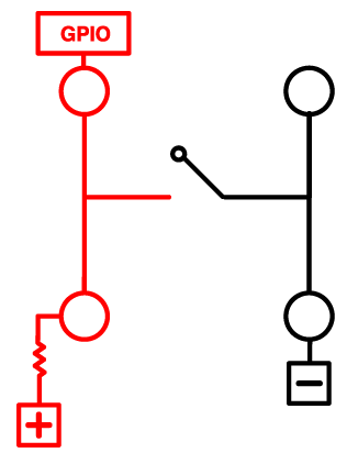
One way to get a logical 0 is to tie the pin to Ground:
Yay! So, now it’s a guaranteed logical zero. While pushing the button, it’s going to be 1 now. Right?
Well, No.
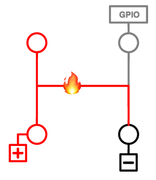
You just created a short circuit. ?
This is where the resistor comes in. To avoid a short circuit, we need to add resistance to our circuit. The resistor keeps things under control.
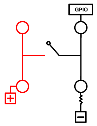
Electricity will take the path of least resistance. Your GPIO will now register a 1 when the button is pressed. Like so:


Woo Hoo! Now we’re working with something.
Now let’s look at the opposite: pull-up resistors. It’s the same thing but in reverse. While the button is not pressed, the GPIO will register a 1. When you pressed the button, the GPIO will be 0.
While not pressed, we have the GPIO connected to positive ( VCC ). So, any current that is there will be pulled-up so that the GPIO registers a logical 1.
It’s important to note here that, electricity always wants to go to Ground. So, when we press the button, the current that’s flowing will flow to Ground. Thus, any current that would have been going to the GPIO goes with it, leaving the GPIO at a logical 0.
? The End.
Why did I write this?
I joined Losant in September of 2016 with no hardware experience. Every single hardware starter kit gives you a button with no explanation of this concept. Hopefully, this helps your light bulb go off too. ?
This only scratched the surface. If you want to dig deeper, check out these resources:
Pull-up Resistors - learn.sparkfun.com
_Another thing to point out is that the larger the resistance for the pull-up, the slower the pin is to respond to…_learn.sparkfun.com
I love feedback. So, please let me know if this could be improved. If I totally missed the ball on this, let me know! I would love to make it better for others.