
By Neo Ighodaro
The Internet of Things (IoT) is changing the way we live, from wearable tech to smart home devices. IoT may sound complex, but in actuality it’s a fairly simple concept to understand. Everyday objects are constantly being transformed into smart devices using sensors and actuators.
In this article, we will build a realtime Arduino ambient light monitor which sends its sensor readings to a web application. We will cover the basics of connecting an Arduino board to the web and sending data as realtime notifications to a web app using Pusher.
This article will act as an introduction to what can be achieved with Arduino and Pusher. It is for those curious about the hardware industry who want to delve into the fun IoT world.
Requirements for building our Arduino and Pusher integration
In this process, I used:
— An Arduino board. MKR1000 board.
— The Arduino IDE.
— Photocell (available here).
— 10k Ohm resistor (available here).
— Breadboard and Jumper Wires.
— A Pusher application — Create one here.
— Composer (available for download at https://getcomposer.org)..)
— Knowledge of PHP.
A breadboard is a board for temporarily prototyping hardware projects. It has nodes that conduct current throughout it.
The jumper wires are used for ensuring continuity between various points on the breadboard that aren’t connected by default.
Getting Started with Arduino
In this section, will set up the Arduino IDE and add internet connectivity to our board. We will find out about choosing the right board and adding internet connectivity to it.
Many of the boards don’t come with internet connectivity, which is something you need to make IoT devices. To add internet connectivity to our board, we have a variety of options to choose from: a shield, micro-chip, or an Arduino board with built-in wireless capabilities.
Note: a shield is basically an extension board that can be placed (mounted) on top of the Arduino board.
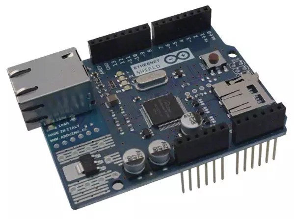
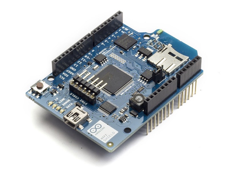
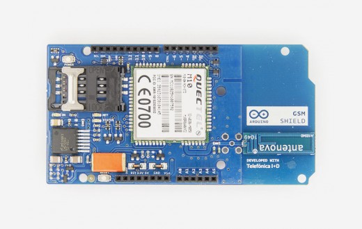
There are many types of shields:
1. Ethernet Shield.
2. WiFi Shield.
3. 3G or LTE Shields.
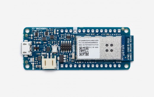
We are going to use the Arduino MKR1000 which comes with an in-built WiFi Chip. This board is available at the Arduino Store.
Next, download the Arduino IDE from here and install it on your computer.
Once the installation is finished, go ahead to install the Board Definition by launching the IDE. Then go to Tools > Boards > Board Manager where we search for and install the definitions for the MKR1000.
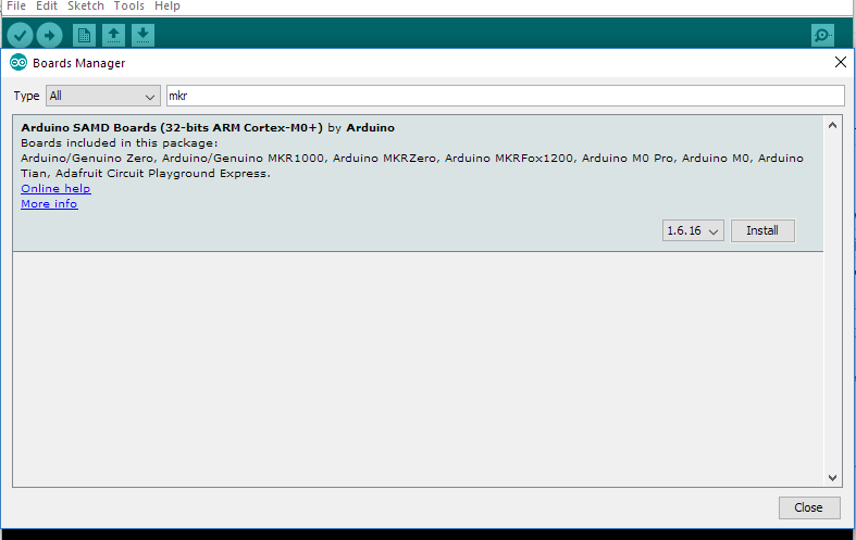
Once the Board Definition is completely installed, go to Tools | Boards and select the newly installed board definition.
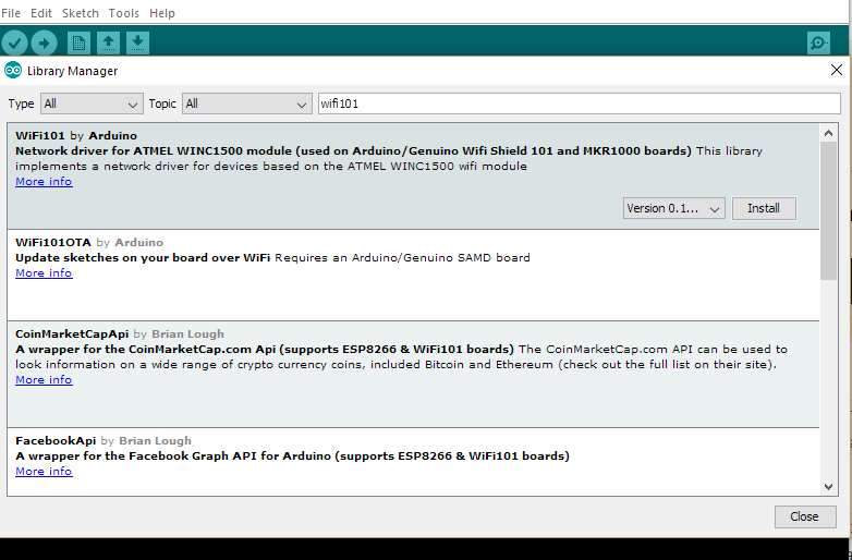
To connect our Arduino Board to the internet, we have to install a library called wifi101. In order to install the library, go to Sketch > Include Library > Manage Libraries, then search for and install wifi101.
We can test that it works by going to Files > Examples > WiFi > ConnectWithWpa. This should generate some code in our sketch. Next, edit the ssid and pass to our router’s SSID and Password:
char ssid[] = "yourNetwork"; // your network SSID (name) char pass[] = "secretPassword"; // your network password int status = WL_IDLE_STATUS; // the Wifi radio's status
Building the Light Monitor in Arduino
In this section, we are going to see how to set up the circuit and measure data coming from the sensors on the MKR1000 board. In addition to the Arduino MKR1000 and the usual breadboard and jumper wires, we are going to need a few extra components.
The photocell is a sensor that allows us to detect light. They are often regarded as Light-Dependent Resistors (LDR), Photoresistors, or CdS cells.
A Photocell is basically a resistor that changes its resistive value (in ohms) depending on how much light is shining onto the squiggly face.
Assembling the components
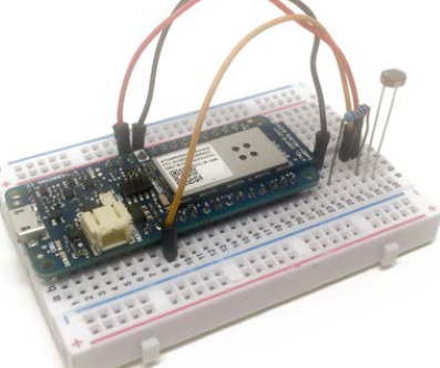
First, place the resistor in series with the photocell on the breadboard, next to the Arduino board.
Now, connect the other end of the resistor to GND on the Arduino board, and the other end of the photocell to the VCC pin of the Arduino board.
Finally, connect the middle pin between the resistor and the photocell to analog pin A0 of the Arduino board. The final result should look like this:
Once this is done, we can go ahead and configure the board to read data coming from the photocell. We will take the readings from analog pin A0 and print them on the serial port for now. The sketch for this part is really easy and should look like this:
We will copy and paste this sketch into our Arduino IDE, then upload it to the board.
Make sure the right board and serial ports are selected.
// Pins int sensorPin = A0; void setup() { // Serial Serial.begin(115200); }
void loop() { // Reading int sensorValue = analogRead(sensorPin); // Display Serial.print("Sensor reading: "); Serial.println(sensorValue); // Wait delay(500); }
You can save the Arduino sketch files to your machine, so you can reference them later. They can be named whatever you like as long as they are uploaded to the Arduino board.
After this is run, we open the serial monitor and immediately observe the readings from the sensor:
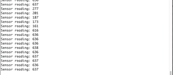
If we put our hands over the sensor, we will see a decrease in the values measured by it. Now let’s focus on creating the web application.
Setting up the web application
In this section, we are going to create a basic web application that collects the data as a GET request and displays it to the users subscribed to that channel in realtime. For realtime display we’ll be using Pusher.
Pusher is a simple hosted API for quickly, easily, and securely integrating realtime bi-directional functionality via WebSockets to web and mobile apps, or any other Internet-connected device.
The first step will be to create a free Pusher account. If you don’t have one, then create your application on the dashboard.
Creating a Pusher application
Create a Pusher account and go to Your apps > Create new app. Fill in your application name, select a cluster, choose JavaScript and PHP, and then we are good to go.
The application set up screen should look something like this:
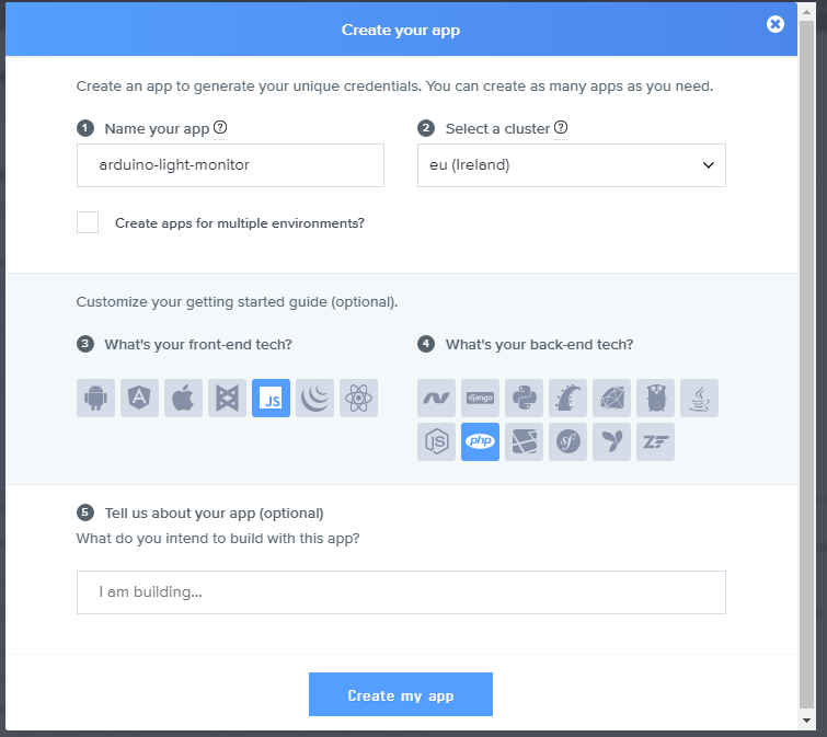
Once done, you will be provided with your App keys.
Setting up our project
We’ll create a folder called arduino-light-monitor in our localhost root directory.
Then, open your terminal and type composer require pusher/pusher-php-server. This will generate a couple of files in our directory.
Create a file called notification.html. Then add the HTML and JavaScript below:
<!DOCTYPE html> <html> <head> <title>Notifications From Light monitor</title> <script src="https://js.pusher.com/4.1/pusher.min.js"></script> <script> //Enable Pusher Logging - don't include this in production Pusher.logToConsole = true;
//Create a new instance of pusher with your credentials var pusher = new Pusher('APP_KEY', { cluster: 'PUSHER_CLUSTER',//if you chose a different cluster replace it here encrypted: true });
//subscribe to a channel you will listen on var channel = pusher.subscribe('light-monitor-channel');
//What happens when light-readings-sent is fired channel.bind('light-readings-sent', function(data){ //gets the ul in the dom var ul = document.querySelector('ul'); //creates a li var li = document.createElement('li'); //Attaches the data received to the text node var itemText = document.createTextNode(data.value); //Append the data to the li li.appendChild(itemText); //Append the li to the ul ul.appendChild(li); }); </script> </head> <body> <ul></ul> </body> </html>
What happens here is we subscribe to a channel called light-monitor-channel then wait until we receive an event called light-readings-sent. Whenever the event is triggered, we append the data received to our list.
We will also create another file called index.php. This is the file that will send the events to the notifications channel. We will add the PHP code below to the file:
<?php require __DIR__ . '/vendor/autoload.php';
$options = array( 'cluster' => 'PUSHER_APP_CLUSTER', 'encrypted' => true ); $pusher = new Pusher\Pusher( 'PUSHER_APP_KEY',// replace with yours 'PUSHER_APP_SECRET',//replace with yours 'PUSHER_APP_ID', //replace with yours $options );
//checks if there is any data sent if(isset($_GET['value'])){ $data['value'] = $_GET['value']; //triggers the event on the channel $pusher->trigger('light-monitor-channel', 'light-readings-sent', $data); } else { echo "Nothing to do"; } ?>
If you need somewhere to host your content, you can go to 000webhost.com and create a free subdomain where you can upload the contents of your arduino-light folder.
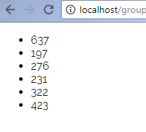
We will test it out by opening notification.html and index.php in two different browsers. When we reload index.php, we should get a new list item added with a value of “Empty request”. If we try index.php?value=123, we should get value 123 added to our notifications list in realtime.
Isn’t that just awesome?
Sending the sensor readings to the web app
Finally, we will look at how to send the data from the Arduino board to the server.
Continuing from the sketch we had before, we just replace this by taking note of the important parts:
// Pins int sensorPin = A0;
char ssid[] = "wifi_name"; //your wifi name char pass[] = "wifi_pass"; // your wifi password int status = WL_IDLE_STATUS;
char server[] = "yourexampleserver.com"; //replace with your localhost or domain
// Create an instance of WiFiClient WiFiClient client;
// We define the interval on which we want to send the data unsigned long lastConnectionTime = 0; const unsigned long postingInterval = 60L * 1000L; //this implies 60,000L the L represents the long datatype
void setup() { // Serial Serial.begin(115200);
// Attempt to connect to Wifi network: while ( status != WL_CONNECTED) {
Serial.print("Attempting to connect to WPA SSID: "); Serial.println(ssid);
// Connect to WPA/WPA2 network: status = WiFi.begin(ssid, pass);
// Wait 10 seconds for connection: delay(10000); }
// you're connected now Serial.print("You're connected to the network"); }
void loop() { if(millis() - lastConnectionTime > postingInterval) { //Measure the light level int sensorValue = analogRead(sensorPin);
//Send the value to the server sendHTTPRequest(sensorValue); } }
void sendHTTPRequest(int sensorValue){ // Close existing connection client.stop();
// Connect & send request if (client.connect(server, 80)) {
Serial.println("connecting...");
// Send the HTTP GET request: client.println("GET /light/?value=" + String(sensorValue) + " HTTP/1.1"); client.println("Host: yourexampleserver.com"); client.println("User-Agent: ArduinoWiFi/1.1"); client.println("Connection: close"); client.println();
// Note the time that the connection was made: lastConnectionTime = millis(); } else { // if you couldn't make a connection: Serial.println("connection failed"); } }
In the code above, we create a connection to the specified WiFi ssid using an instance of WiFiClient. We will use this connection to interact with our remote server.
In the setup``() function, we deal with the initialization of the Serial and connection to the WiFi network specified by the ssid and pass variables above.
In the loop``() function we check if we are in the posting interval. Then, if we are, we take the reading and make a call to the sendHTTPRequest function defined below it.
In the sendHTTPRequest``() function, we accept a parameter called sensorValue. Because Arduino runs the code in a loop, the first thing to do is to stop any previous opening of the client connection with the statement client.stop(). This will stop connections from being created and will keep them from being discarded after they have been used.
Next, we try to connect to the server defined in the variable server[]. We check if the connection can be established, and if not we print to the Serial “connection failed”. Once the client is connected, we send the sensor pin value through the URL to our web application.
If we test this out now, we will have the light sensor reading every minute.
Conclusion
We have successfully built a light monitor using Arduino and Pusher. If you enjoyed this tutorial and would like to go from zero to hero in the IoT world, you should check out the book “Internet of Things with Arduino Cookbook” by Marco Schwartz. It contains over 60 recipes which will help you build smart IoT solutions and will surprise you with captivating IoT projects you thought only existed in James Bond movies.
If you have any questions or other ideas on integrating IoT with Pusher, please leave a comment below!
This was originally published on our blog.