By Jared Wolff
This post is originally from www.jaredwolff.com
There’s something that always goes wrong with a first revision circuit board design. No matter how long you spend imagining how a circuit will work, it will bork in the most unexpected ways.
In the case of my latest project, I overlooked a critical pice of circuitry. My revelation? Turns out you can’t reliably shunt 375mW of power into a 100mW resistor. ? Unfortunately, as you guessed it, this would require rework.
So, in my quest to make the right prototyping solution, I thought: “Why not share the things going through my head right now”
And thus, this blog post was born. ?
The (Solder-less) Breadboard
When you are time constrained the solder-less breadboard is a go-to. This type of electronic prototyping is painless but there are some drawbacks. Most notably, it does not play well with analog optimization. I’ll get into that a little later in this post.
I recently assembled an indoor air quality PM2.5 sensor and interfaced it with a Particle Argon. I assembled it using wire wrap. but it was a complete disaster. In comparison, the solder-less breadboard kept things organized and good looking to boot.
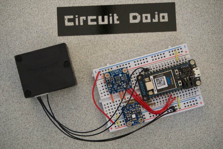
Electrical engineers come to love (or hate) bread boards early in their educational pursuits. For some it can be an outlet to get creative and make beautiful layouts. Many first year computer engineering students take pride in their breadboard designs. So much so that their breadboards looked as if assembled by a robot.
These days though, I don’t wire together huge digital logic circuits like in college. I do use solder-less breadboards though to make solid connections to development modules. As you can see int the above picture, I’ve used 3 separate boards which are all available across the web. Connecting them together took approximately 10 minutes as most. It took me approximately 15 minutes to assemble the wire wrap version.
The Breadboard ?
Sometimes a solder-less breadboard is great but it isn’t meant for every situation. What if you need something to be reliable? What if you’re working with high voltages? If you’re looking for more but don’t want to jump to making your own PCB, this is your next stop.
Creating a solderable breadboard is not too dissimilar to a solder-less version. It took me about 20 minutes to assemble the circuit in the picture below.
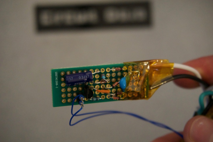
The breadboard above is the replacement zero-cross circuit mentioned earlier. Considering I was working with line voltage I was very cautious about the assembly.
So after triple checking my work. I plugged it in and you know what?
It worked like a charm.
Breadboards take some time to plan but when you get them right, they’re as good as a normal circuit board.
Furthermore, you don’t always have to solder every single connection together. I created this JTAG level shifter board about a year ago. That way I could run my circuit boards in ranges from 1.8V to 5V and have it work with the standard 3.3V programmer.
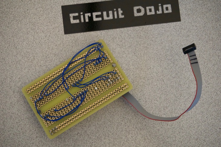
In this case, I used solder and wire wrap. connections. For future projects I plan on using the JTAG level shifter board I designed not too long ago. It’s 1/5 the size and as functional as the one above.
Going Beyond The Breadboard
I am definitely not afraid of assembling my own circuit boards. There’s a time and a place for that. There are still some things you can do before ever having to open up your schematic capture program.
Always consider the use of circuits and development platforms that already exist!
Being smart about your design process pays dividends to your future self. It helps you focus on the sticky problems rather than the trivial distraction. If you are in need of a pre-designed circuit board Sparkfun and Adafruit are great resources. They’ve already created the breakout boards for ICs that interest most makers.
To put the icing on the cake, in most cases, these circuit boards are diiiiirt cheap.
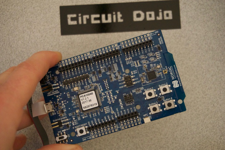
Companies like TI also make development boards. The board are reasonably priced and usually in stock on Digikey and their web store. Some of my favorite manufacturer development boards include the NRF52DK and the LT3092EDD. I use them both often and for some very good reasons.
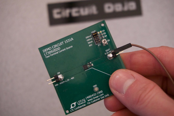
The LT3092EDD is my go to for regulating current from a variable voltage source. No mater what the input voltage, it will shunt the current anywhere from 0-200mA. You can place several LT3092 in parallel increasing the current capability. I use it for static discharge tests and validation that have a need for constant current sinks.
As for the NRF52DK, not only can I develop on this board but I can use it as a programmer too. With tons of ways to expand off the board, it’s doesn’t leave my desk very often.
But what if there isn’t a development board?
Sometimes neither type of breadboard is great. This is especially true if you’re prototyping is dependent on the shape and form of the copper on your board. I’d expect if you did breadboard a switching power supply you may get some very unintended operation.
Laying out a power supply circuitry tends to be a bit more complex than say a digital signal. Yes, it will work with a tiny trace connecting two parts, will it work well? Unlikely.
Below is a design which allows for current transfer to the inner power layer. As you could imagine, a skinny trace and one via may work. In reality, they’d act more like a resistor high current situations.
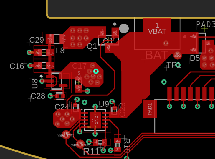
Although you may get better connections, you run the risk of higher costs. Plus is much harder to change your circuitry down the road. Things get more complicated when the parts get smaller and the signals pushed inside. It’s not impossible though..
When changes are necessary, my most used tools are wire wrap wire or coil wire and my trusty X-acto knife. You can use the former to make the connections and the later to break connections. This does require a steady hand and patience but it’s possible.
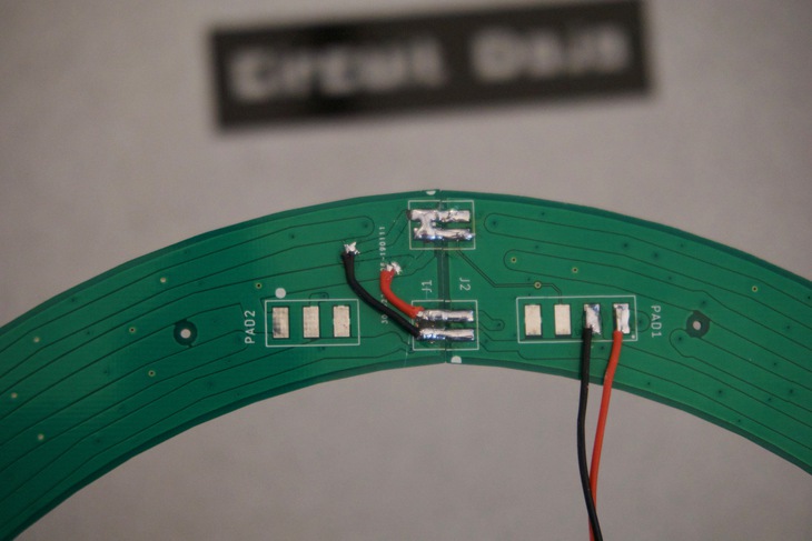
In the picture above, I cut away thermal traces around pads and reconnected to another set of traces. You may have to take my word on this one considering it’s hard to tell from the picture! I did all the work under a microscope to avoid error.
You can du it ?
There’s a handful of ways to assemble a circuit. It’s all up to you how you want to get it done. I’ve seen some very cool circuit art out there that accomplishes the same thing as a bread board.
If you haven't already noticed, I ended up going with a breadboard design. It was faster to assemble and test versus ordering a whole new circuit board. I will likely spin another board in the future. In the meantime this little breadboard should do fine.
I use all these techniques when it comes to working with my clients. No technique is off the table and it always usually benefits everyone. In reality, a breadboard always evolves into a circuitboard of some kind. It’s good to know though that the circuit will work before turning it into a costly prototype.
So until next time, when you find yourself with the same quandry remember your options.
Have fun!