

Coding an LED Light is introductory project that shows you how software and hardware interact with each other. It's a simple project you can complete in a weekend that'll help you learn some basic aspects of hardware.
By the end of the project, you will code your own LED light, have the knowledge to manipulate the LED to on/off in intervals you choose, and learn basic principles of hardware.
The Elegoo Uno starter kit has all the hardware as well as instructions you need to make a simple LED Light. The LED Light is the first project offered with their kit.
Elegoo Uno comes with many other projects and takes you through from beginner to advanced projects. Each project in the box advances your skills in a simple, easy to follow way.
Components You'll Need
Elegoo Uno R3
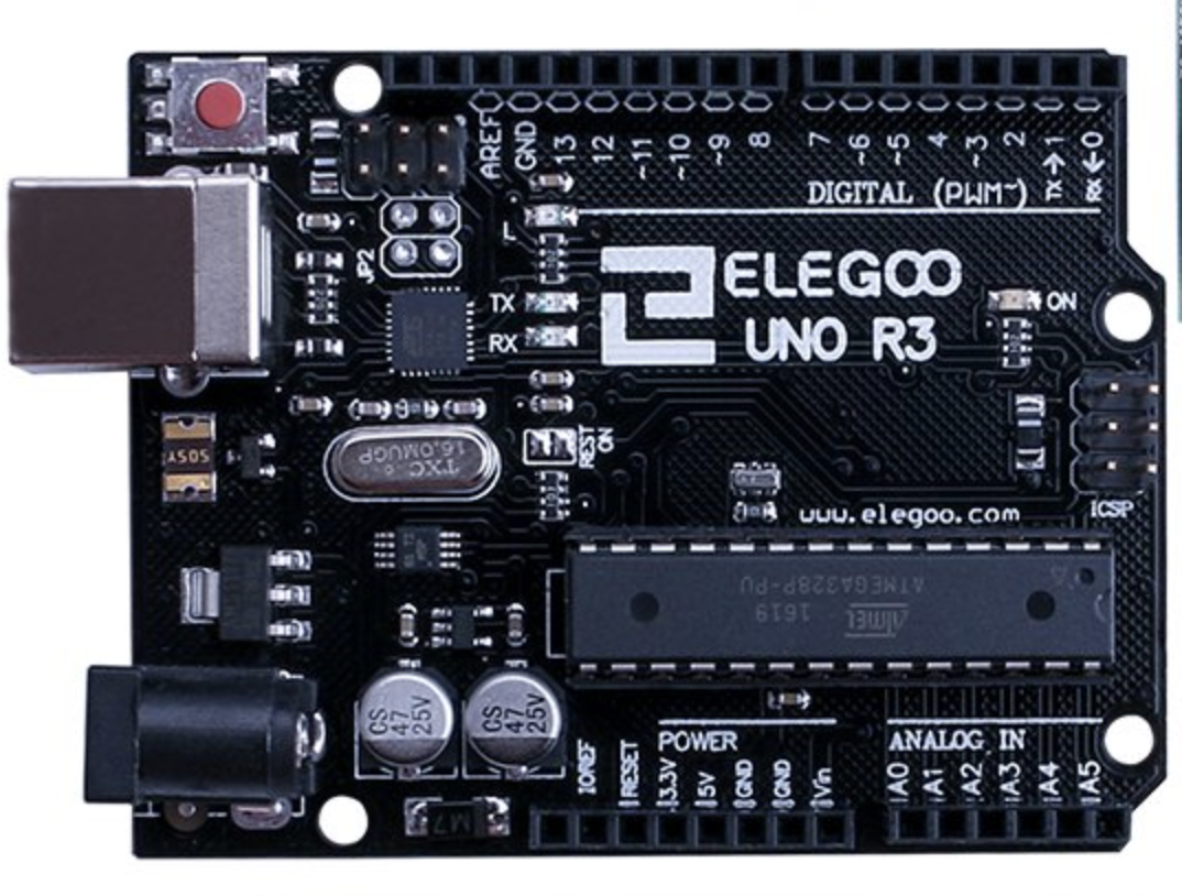
Elegoo Uno R3
The Elogoo Uno R3 is a microcontroller board. Microcontrollers are embedded inside devices to control the actions and features of a product. They are compact integrated circuits designed to control operations.
The microcontroller that is included in the Elogoo Uno R3 has 14 digital input/output pins, 6 analog inputs, a USB connection, a power jack, and a reset button. This board has everything you need to support the microcontroller. Simply plug in the USB Cable to turn the microcontroller on.
USB Cable

USB Cable
You need a USB Cable to connect the Elegoo Uno R3 to your computer and turn it on. USB stands for Universal Serial Bus. The USB is used to connect your computer to devices such as digital cameras, printers, scanners, and external hard drives.
In our project, we will use a USB cable to connect our microcontroller to our computer.
LEDs
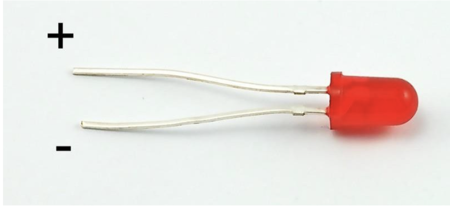
LED Light
LED stands for light emitting diode. It has a positive and negative lead. The longer side is the positive lead.
How to assemble the components
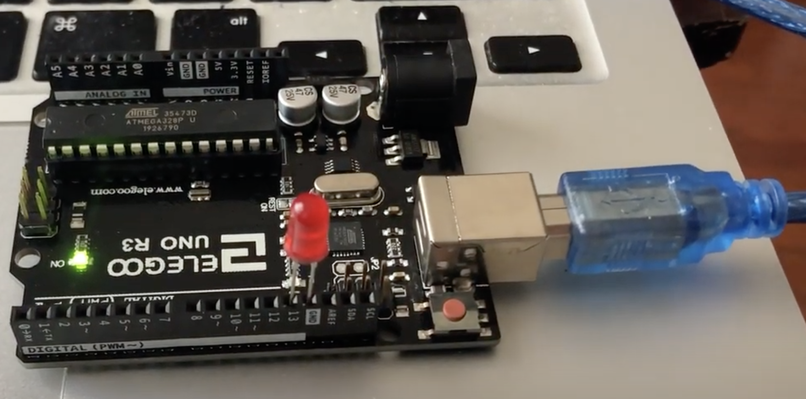
In this project, we are only going to make the LED blink.
First, we need to plug in the USB Cable to the board and then the computer.
Then we need to plug in the LED to GND (GND is the reference point in an electrical circuit from which voltages are measured, and is a common return path for electric current) and the 13 input on the board.
Code to make the LED flash on/off:
After the microcontroller board is plugged into the computer and the LED is on the board itself, we need to write some simple code to make the LED blink.
// the setup function runs once when you press reset or power the board

void setup() {
  // initialize digital pin LED_BUILTIN as an output.
  pinMode(LED_BUILTIN, OUTPUT);
}

// the loop function runs over and over again forever
void loop() {
  digitalWrite(LED_BUILTIN, HIGH);   // turn the LED on
  delay(1000);                       // wait for a second
  digitalWrite(LED_BUILTIN, LOW);    // turn the LED off
  delay(1000);                       // wait for a second
}
The code above basically turns the LED on for 1 second and then turns it off for one second.
This function is in a continuous loop. The digitalWrite is a function that takes in 2 parameters, LED_BUILTIN and HIGH || LOW . The loop basically takes in the LED, and then turns the volt to HIGH which turns it on. Then after 1 second it turns the same LED off by turning the volt to LOW .
Here's the Final Product:
The goal of this little LED Light Coding project was to introduce you to elementary principles of how hardware and software can be combined. I hope you enjoyed it!