

Potentiometers are used in various electronic circuits and systems. You can use them in electronic devices to control volume, brightness, motor speed, voltage regulation, and so on.
You've most likely used a potentiometer before with appliances like radios, microwaves, blenders, electric fans, game controllers, and others.
They are generally used to provide or control different ranges of variable resistance in electronic circuits.
In this article, you'll learn the following:
- How to connect a potentiometer to an Arduino board.
- How to get the values of a potentiometer.
- How to control the brightness of an LED using a potentiometer.
You can also watch the video version of this article here:
Hardware Components
Here are the hardware components you'll need to follow along:
- Arduino board.
- Potentiometer.
- Breadboard.
- LED.
- 1K Ohm resistor.
- Jumper wires.
How to Connect a Potentiometer to an Arduino Board
The potentiometer is made up of three terminals: two outer terminals and the middle terminal. Either of the outer terminals can be connected to either 5V or GND (ground). That is:
- If you connect the left outer terminal to 5V, you have to connect the right outer terminal to GND.
- If you connect the left outer terminal to GND, you have to connect the right outer terminal to 5V.
The middle terminal serves as the output terminal. We'll connect it to an analog pin. You can read the varying values of the potentiometer from the output terminal.
Here's the circuit diagram:
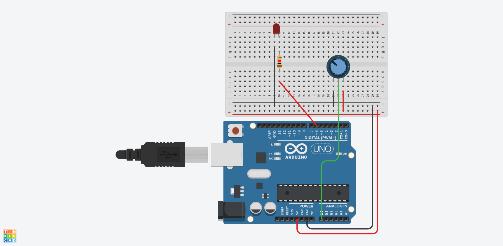 circuit diagram
Here's how the potentiometer was connected in the diagram above:
- The left outer terminal of the potentiometer was connected to GND.
- The right outer terminal was connected to 5V.
- The middle terminal (output terminal) was connected to analog pin A0 on the Uno board.
Here's how the LED was connected:
- The shorter leg of the LED was connected to GND.
- The longer leg was connected to digital pin 6 through a 1K Ohm resistor.
Make sure to connect the LED to a digital pin with the ~ symbol. Such pins support pulse width modulation, which lets you send analog signals to digital pins.
int potPin = A0;
int potValue = 0;
int brightness = 0;
int ledPin = 6;

void setup() {
  Serial.begin(9600);
  pinMode(ledPin, OUTPUT);
}

void loop() {
  potValue = analogRead(potPin);
  brightness = (255.0/1023.0)*potValue;
  analogWrite(ledPin, brightness);
}
Let's break down the code.
Initialize Variables
We started by initializing our variables:
int potPin = A0;
int potValue = 0;
int brightness = 0;
int ledPin = 6;
The potPin variable has a value of A0. This represents the A0 pin connected to the output pin of the potentiometer.
We then declared a potValue variable, which will be used to store the values from potPin.
The brightness variable will be used to control the brightness of the LED.
The LED pin was connected to digital pin 6 on the Uno board, so we initialized a ledPin variable with a value of 6: int ledPin = 6;.
Serial Monitor and pinMode
Next, in the loop() function, we initialized the serial monitor and set the LED pin to serve as an output pin:
void setup() {
  Serial.begin(9600);
  pinMode(ledPin, OUTPUT);
}
Create Logic to Control LED Brightness
In the loop() function, we have three lines of code:
void loop() {
  potValue = analogRead(potPin);
  brightness = (255.0/1023.0)*potValue;
  analogWrite(ledPin, brightness);
}
In the first line, we used the analogRead() function to read the value of potPin. The read values were assigned to the potValue variable.
At this point, if you print potValue to the serial monitor using Serial.println(potValue);, you'll get a range of values from 0 to 1023 when you tune the knob of the potentiometer.
For the brightness variable, we converted the values from the potentiometer to fall with the range of 0 to 255: brightness = (255.0/1023.0)*potValue;. This is because the analogWrite() function only accepts values within that range, and not the default 0 to 1023 that the potentiometer produces.
Lastly, we used the analogWrite() function to send values to the LED: analogWrite(ledPin, brightness);.
The analogWrite() function's first parameter is the ledPin, which denotes the pin where the values should be sent. The second parameter is brightness, which denotes a range of values to be sent to the LED (ledPin).
When you upload the code to your board, the LED should have varying levels of brightness as you tune the potentiometer.
Conclusion
In this article, you learned how to control the brightness on an LED using a potentiometer. You also saw how to connect the components to digital and analog pins on an Arduino board.
Finally, you learned about how to make the components work together using code.
You can find the code for this project here. You can watch the video version here.
Check out my blog for articles about embedded systems, IoT, and web development.
Happy coding!