
Web Real-Time Communication (or WebRTC) is the open standard browsers use to send audio, video, and data straight to each other. There's no plugin or native app, nothing beyond an API that every browser already ships.
WebRTC covers the media path: once two peers have found each other, everything from codec negotiation to encoding to transport is handled. What it never covers is the finding part.
This article discusses the three APIs that make up the spec, why signaling and NAT traversal live outside it, an implementation of a signaling server at scale, and the mesh/SFU/MCU tradeoff that decides how the media itself scales.
Table of Contents
The Building Blocks: Three APIs, One Gap
WebRTC exposes three JavaScript APIs to do this:
RTCPeerConnectionnegotiates codecs between the two peers and handles encoding, decoding, and transmitting the media stream once a connection exists.MediaStreamgets it something to send, wrapping access to a webcam or microphone.RTCDataChannelruns alongside the media connection for anything that isn't audio or video, chat messages, file chunks, game state, or any application data that doesn't need a codec.
None of them know how to find a remote peer on their own. That's the part WebRTC leaves out entirely.
Signaling and the Offer/Answer Exchange
Before two peers can exchange media, they have to exchange a description of what they're capable of: codecs, network info, media types, and encoded as SDP (Session Description Protocol).
WebRTC ships no mechanism for actually delivering that description between peers. That's signaling, and the spec deliberately leaves it up to whoever's building on top, typically over WebSockets or HTTP long polling.
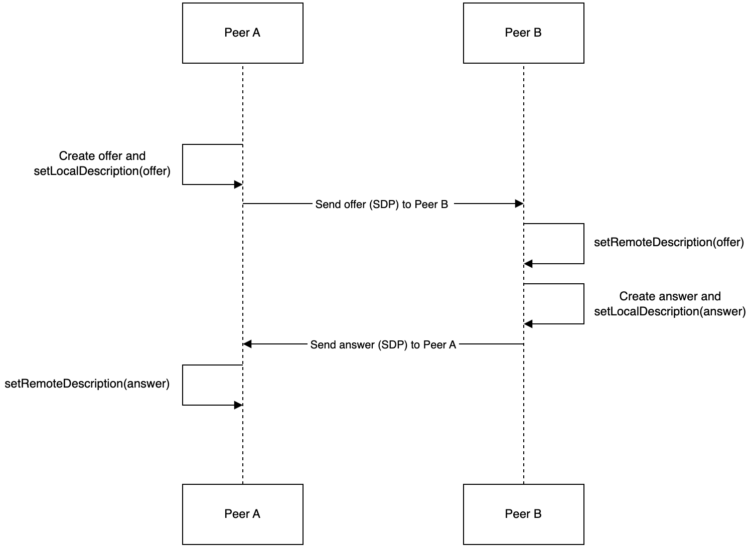
The exchange itself follows a fixed shape, an offer from the peer initiating the call and an answer from the peer receiving it:
// Peer A: create and send the offer
const pc = new RTCPeerConnection({ iceServers });
const offer = await pc.createOffer();
await pc.setLocalDescription(offer);
signalingChannel.send({ type: 'offer', sdp: pc.localDescription });

// Peer B: accept the offer, respond with an answer
await pc.setRemoteDescription(offerFromA);
const answer = await pc.createAnswer();
await pc.setLocalDescription(answer);
signalingChannel.send({ type: 'answer', sdp: pc.localDescription });

// Peer A: complete the handshake
await pc.setRemoteDescription(answerFromB);
setLocalDescription and setRemoteDescription are the only two calls doing any real work here. Everything else is just getting the SDP blob from one peer's signaling connection to the other's.
NAT Traversal: ICE, STUN, and TURN
An SDP exchange tells each peer what the other supports. It doesn't tell them how to reach each other, since most devices sit behind NAT or a firewall with no directly routable address.
ICE (Interactive Connectivity Establishment) is the piece that solves that, gathering every address a peer might be reachable at and testing them until one works. Those addresses, called candidates, come from two kinds of servers: STUN (Session Traversal Utilities for NAT) and TURN (Traversal Using Relays around NAT).
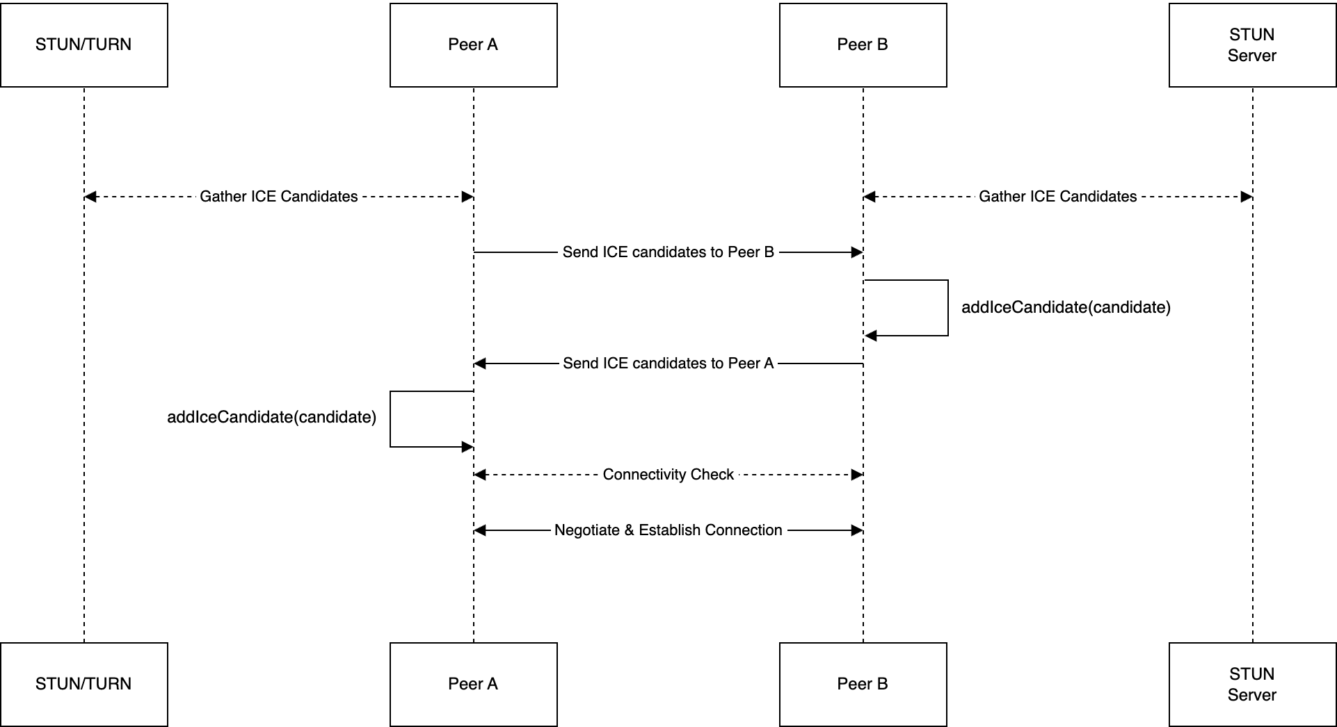
The diagram shows a single peer gathering three candidate types in parallel: a host candidate from its own network interface, a server-reflexive candidate returned by a STUN server (the public IP and port its NAT mapped it to), and a relay candidate allocated on a TURN server. All three are sent to the remote peer as ICE candidates, and whichever pairing connects successfully is the one used for the call.
STUN handles the common case: a peer asks a STUN server what public IP and port the NAT mapped it to, and uses that as a candidate address.
TURN is the fallback for when STUN isn't enough. Symmetric NAT and some firewall configurations block direct connectivity outright, so a TURN server relays traffic between the two peers instead. It works in every network configuration STUN can't, at the cost of routing every packet through a third server instead of directly between peers, adding latency and consuming server bandwidth for the duration of the call.
Candidates can be exchanged two ways. First, regular ICE can wait until every candidate is gathered before sending any of them. This is simple but adds latency up front: the connection can't start negotiating until the slowest candidate finishes gathering.
Second, trickling ICE sends each candidate the moment it's found, so negotiation starts on whichever candidate arrives first instead of waiting on all of them. But this comes at the cost of needing both peers' signaling and ICE implementations to handle candidates arriving incrementally rather than all at once.
For time-sensitive applications, trickling is worth the added implementation complexity. Most modern WebRTC stacks support it by default.
// Sending side: forward each candidate the moment ICE finds it
pc.onicecandidate = (event) => {
  if (event.candidate) {
    signalingChannel.send({ type: 'ice-candidate', candidate: event.candidate });
  }
};

// Receiving side: add each candidate as it arrives, don't wait for the rest
signalingChannel.on('ice-candidate', ({ candidate }) => {
  pc.addIceCandidate(candidate);
});
An Example Implementation
To see where these pieces actually cost something at scale, I built a signaling server MVP:
Node.js for the server, since its single-threaded event loop handles many concurrent WebSocket connections without the overhead of a thread per connection, and
Express for routing and Socket.IO layered on top for the client connection, falling back to HTTP long polling automatically when a client's network blocks WebSockets outright.
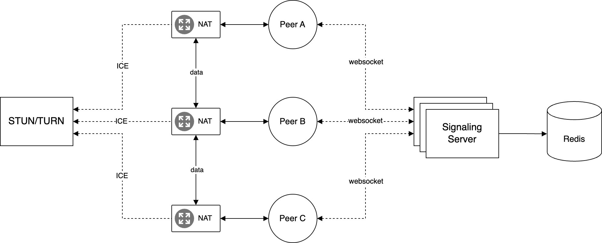
The diagram shows browser clients connecting over WebSocket (falling back to HTTP long polling) to an Application Load Balancer, which routes each connection to one of several Socket.IO server pods running in Docker containers on EKS. Every pod shares the same Redis cluster for room state, so it doesn't matter which pod a given client lands on.
Room-to-peer mapping lives in Redis (Amazon ElastiCache), which only needs to answer "who else is in this room" fast, not persist anything past the call.
Sticky sessions on the ALB are what make this work at all. A WebSocket connection has to stay pinned to the same signaling server instance for its entire lifetime, so every request from one client needs to land on the same backend pod every time.
Stripped to the events that matter, the server itself is a thin relay. It never looks inside an SDP blob or ICE candidate, it just tracks room membership in Redis and forwards messages to the right socket:
io.on('connection', (socket) => {
  socket.on('join', async (roomId) => {
    socket.join(roomId);
    await redis.sadd(`room:${roomId}`, socket.id);
    socket.to(roomId).emit('peer-joined', socket.id);
  });

  socket.on('offer', ({ target, sdp }) => {
    io.to(target).emit('offer', {
      from: socket.id,
      sdp,
    });
  });

  socket.on('answer', ({ target, sdp }) => {
    io.to(target).emit('answer', {
      from: socket.id,
      sdp,
    });
  });

  socket.on('ice-candidate', ({ target, candidate }) => {
    io.to(target).emit('ice-candidate', {
      from: socket.id,
      candidate,
    });
  });

  socket.on('disconnecting', async () => {
    // Copy the rooms before Socket.IO removes the socket from them.
    // socket.rooms also contains a private room named after socket.id.
    const rooms = [...socket.rooms].filter(
      (roomId) => roomId !== socket.id
    );

    for (const roomId of rooms) {
      socket.to(roomId).emit('peer-left', socket.id);
      await redis.srem(`room:${roomId}`, socket.id);
    }
  });
});
join adds the socket to a room and records it in Redis so other server instances can see it. offer, answer, and ice-candidate all do basically the same thing: they take a target socket ID and forward the payload without interpreting the SDP or ICE data.
The disconnecting handler performs cleanup before Socket.IO removes the socket from its rooms. It first copies the current room IDs, excluding the socket's private room, then tells the remaining peers that the connection has left and removes the peer from each corresponding Redis set.
Copying the room IDs up front is important because the handler performs asynchronous Redis operations, and the socket's room membership is cleared as disconnection completes.
Without this cleanup, Redis could keep listing a peer as present after its socket is gone, leaving stale room state behind and causing the remaining peers to wait for signaling messages or ICE candidates that will never arrive.
Benchmark
Ten replicas, 1 CPU and 512 MB memory each, driven for 60 seconds at 100k requests per second:
| Event | Completed | Failed | Availability |
|---|---|---|---|
| Join room | 99991 | 9 | 99.991% |
| SDP offer | 99968 | 32 | 99.968% |
| SDP answer | 99982 | 18 | 99.982% |
| Trickle ICE | 99977 | 23 | 99.977% |
Every event type held above 99.96% availability under load, averaging 99.98% across the four. Signaling is lightweight by design: it's moving small JSON payloads over an already-open connection, not media, so the actual bottleneck for this kind of server is almost always connection count and memory per connection rather than CPU.
Scaling the Topology
Signaling only sets up the connection. What happens to the actual media traffic once two or more peers are talking is a separate, harder problem, and it comes down to a choice between three topologies.
Peer-to-peer (P2P)
The direct approach connects every peer to every other peer: a full mesh. It needs no media server at all, which makes it cheap and keeps every stream end-to-end, but the number of connections grows quadratically: n(n-1)/2 for n peers. Six peers means 15 connections, and every peer uploads its own stream to the other 5 while downloading their 5 streams in return.
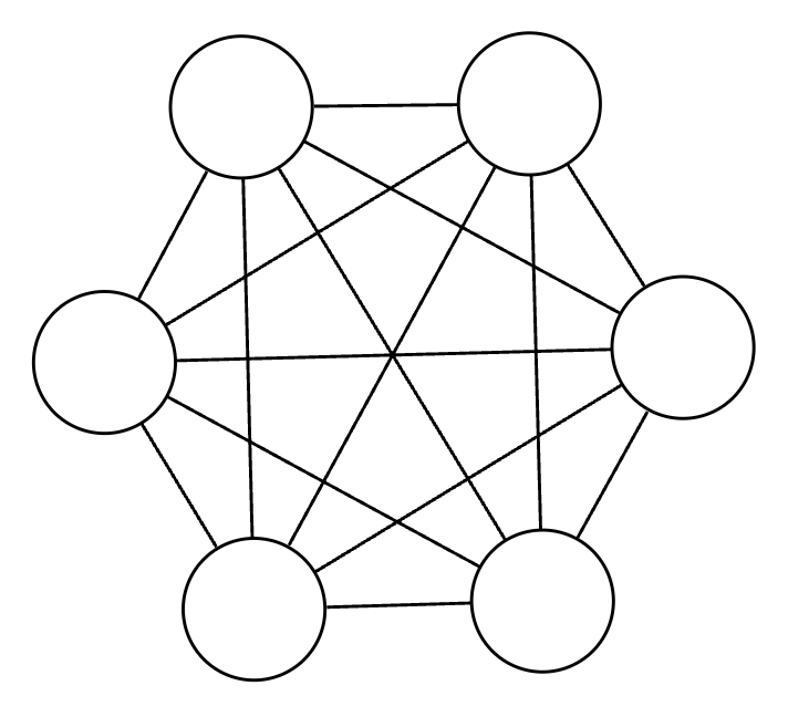
At 1 Mbps per stream, each peer in a 6-person mesh call is pushing 5 Mbps up and pulling 5 Mbps down, just to sustain their own participation. That cost is what makes mesh impractical past a handful of participants. It isn't a server limit, it's every single client's own upload bandwidth and CPU running out first.
Selective Forwarding Unit (SFU)
An SFU collapses that mesh into a star: every peer sends its stream once, to a central server, which forwards each stream to whichever other peers need it. Upload drops from (n-1) connections to 1 regardless of call size, while download stays at (n-1) since the SFU still has to hand each peer everyone else's stream individually.
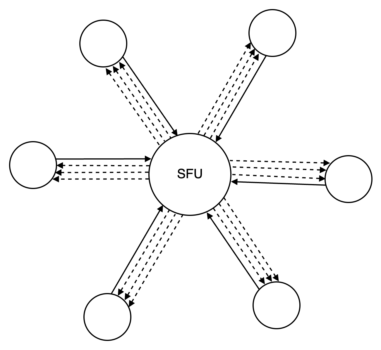
Total connections drop from quadratic to linear, n instead of n(n-1)/2, and a peer's upload cost stops scaling with call size entirely. The SFU itself becomes the thing that has to scale instead, but forwarding packets is far cheaper than decoding and re-encoding them, which is the trade an MCU makes instead.
Multipoint Conferencing Unit (MCU)
An MCU takes it a step further: every peer's stream is decoded, mixed into one composite stream server-side, then re-encoded and sent back down as a single stream. Upload and download both drop to 1 connection per peer. This is the lowest bandwidth cost of the three approaches.
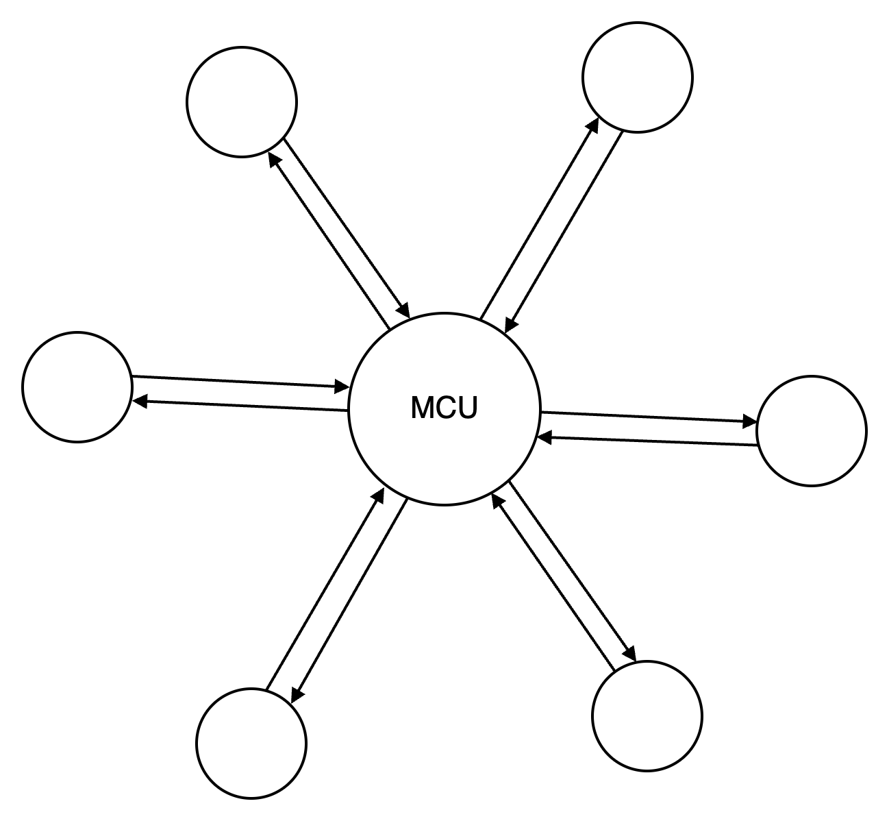
That bandwidth reduction is bought with real-time transcoding for every participant in every call, decode, mix, encode, continuously, which is CPU and often hardware-encoder bound in a way an SFU never is. It also fixes the output layout server-side: a client can't rearrange who's shown where the way it can when it receives separate streams from an SFU.
| Approach | Upload / Download | Bandwidth | Connections |
|---|---|---|---|
| P2P | 5 Mbps / 5 Mbps | 30 Mbps | 15 |
| SFU | 1 Mbps / 5 Mbps | 12 Mbps | 6 |
| MCU | 1 Mbps / 1 Mbps | 12 Mbps | 6 |
For most group calling products, SFU wins. The bandwidth savings over mesh still hold, and clients keep control over their own layout. MCU earns its cost back in narrower cases, and recording is the clean example: with every stream already combined server-side, writing the result to S3 is one file write instead of a client-side composite of n separate streams.
What Else Matters at Scale
Topology isn't the only thing that breaks under real traffic. Connectivity, signaling load, browser support, security, and reliability each have their own failure mode once production traffic hits the system.
Connectivity
Some networks block STUN and TURN traffic outright unless it looks like ordinary HTTPS. Running STUN and TURN over TLS on standard ports, and placing STUN servers geographically close to clients, improves how often a direct connection succeeds before falling back to relaying through TURN.
Signaling Under Load
Because the signaling server holds no media, scaling it is an ordinary web-service problem. A Horizontal Pod Autoscaler reacting to CPU and memory handles it the same way it would any other stateless service once sticky sessions are in place.
Browser Support
Older browsers can lack full WebRTC support. A polyfill like Adapter.js papers over the API differences between browser versions instead of branching application code per browser.
Security
WebRTC encrypts media by default: DTLS handles the key exchange, while SRTP encrypts the audio and video packets. But that's transport encryption between peers and relays, not end-to-end encryption between users.
Enforcing HTTPS and WSS on the signaling channel, requiring auth on TURN servers, rate-limiting the signaling API, and enabling Perfect Forward Secrecy close the gaps DTLS/SRTP don't cover on their own.
Reliability
WebRTC runs over UDP, which drops and reorders packets with no retransmission. Forward Error Correction sends redundant data alongside the original stream, so a receiver can reconstruct a lost packet from the redundancy already in hand instead of waiting on a retransmit that would arrive too late to matter for real-time media anyway.
Next Steps
In this article, you learned the three APIs WebRTC exposes, why signaling and NAT traversal live outside the spec, how to benchmark a signaling server under load, and the bandwidth tradeoffs between mesh, SFU, and MCU topologies.
None of this is specific to video calling. Any product built on WebRTC like screen sharing, live collaboration, or cloud gaming runs into the same signaling, NAT traversal, and topology decisions.
You can also review the resources below to keep learning: