
By Armstrong Subero
The world as we know it was recently taken by storm. That storm was the outbreak of the COVID-19 pandemic. This has in turn created a shortage of ventilators world wide which has led many people to foray into the world of ventilator design.
There is just one problem: many people are basing their designs around the Arduino platform. While this may be good for a proof of concept, you do not want to use it for actual life support unless absolutely necessary.
This is because platforms like the Arduino were designed as a platform to be used in a learning environment. They were not designed for the real time, safety-critical design that is required to build ventilators.
However, there are some workarounds you can employ to adapt the platform for use in a makeshift emergency ventilator if one isn't available.
In this post we will discuss real time systems and safety-critical systems. Hopefully you can use some of these principles in your own ventilator control system designs to improve their safety and reliability.
Since the target audience is mainly web developers trying their hand at embedded design, I will try to make this post as self contained as possible. Join me as we dive from the browser into the realm of embedded systems design and move closer to the hardware to design our ventilators.
Embedded Systems
For all its usefulness a ventilator is simply an embedded system. An embedded system is a system that is designed to carry out one function and to perform it well, with high reliability and minimal user intervention.
To accomplish this an embedded system consists of two components: a hardware system as well as a software component to run the hardware configuration.
A classical embedded system is typically powered by a control device which generally integrates RAM, ROM, as well as a host of embedded peripherals on board to allow the system to accomplish its task.
Modern embedded systems can sometimes be based around an applications processor, which may integrate a GPU, multiple CPU cores, multimedia codecs and other devices. Though applications processors can be used in embedded systems, they are mainly used in general purpose computing systems such as a smartphone.
The software that runs on an embedded system is called firmware. It is called firmware because once written into ROM, it is not expected to change frequently.
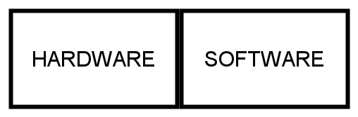 Components of An Embedded System
Think of a ventilator. Its main purpose is to provide mechanical ventilation to keep patients alive. It performs one function and does it with a high degree of reliability, to such an extent that it can be used as a life support system. Very rarely do you find someone changing the firmware in such a device once deployed.
The Hardware Component
As stated previously, the embedded system has a hardware component which integrates RAM, ROM and other devices in one package. This device is called a microcontroller.
There are several popular microcontrollers today. The PIC and AVR from Microchip Technology and the STM32 from STMicroelectronics are the most popular. The classic Arduino uses an AVR microcontroller at its core.
Regardless of the manufacturer, the microcontroller will consist of a processor core, memory and a means to provide input and output also known as I/O.
Microcontrollers also consist of memory which are divided into two categories: data memory and program memory.
Data memory is memory that is used to store data that will be used by the microcontroller during run time. It is typically a few tens to a few hundred kilobytes of SRAM. Data memory is volatile and is lost when power is removed from the device.
Program memory on the other hand, actually stores the memory that will be used by the microcontroller. It consists of Flash (think the memory in your USB flash drive) or FRAM (Ferroelectric RAM) and is not volatile. The size of program memory typically ranges from a few bytes to a couple of megabytes on modern systems.
The Input and Output (I/O) pins on the microcontroller are what allow the device to communicate with external devices such as sensors and other chips that perform various functions such as memory expansion and even adding additional I/O to the device.
A microcontroller will also integrate peripherals for performing analog to digital (A to D) and digital to analog (D to A) functionality.
This is because our world is analog in nature and Analog to Digital Conversion (ADC) will convert real world data into a format our microcontroller can process. If you have a voice recorder, a microphone sensor together with a microcontroller will convert your voice into a digital format and store it.
The microcontroller may also have means to perform Digital to Analog Conversion (DAC) whereby digital data can be converted into an analog format that we can utilize in the real world.
In our voice recorder example, this would be applicable when you must play back your recorded voice. The stored digital information is converted to sound we can detect in our analog world.
When we combine all this we get a block diagram of typical microcontroller hardware.
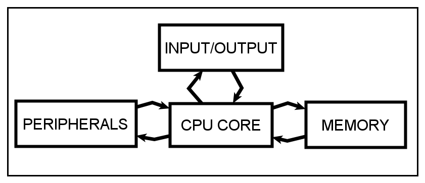 Crude Microcontroller Block Diagram
Now that we have a basic understanding of the hardware, let's look at the software component.
The Software Component
As great as your hardware is, without the software to control it, it's as useful as a paper weight. Software in embedded systems typically fall into three basic categories:
- cyclic execution systems,
- finite state machine based systems, and
- systems build using a real time operating system.
The difference between these three types of software systems is based on the way they handle tasks. When we speak about tasks, what we are talking about is the smallest unit of execution within your firmware.
Cyclic Execution Systems
A cyclic execution system works by having all the program tasks contained in an infinite loop. These systems have one main program entry point, and then the system cycles through a list of tasks. This is the simplest type of firmware design and is used for basic systems.
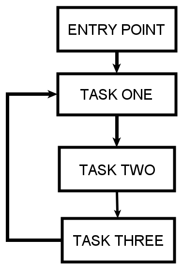 Cyclic Execution System
This system will have a program entry point which would typically configure hardware and set up systems clocks and basic bring up tasks. Once the program enters into the infinite loop, it will perform Task one, then Task two and finally Task three.
Finite State Machine
While the cyclic based execution system is simple and effective for most tasks, sometimes you need a little more control over program flow. When this occurs a designer may use what is known as a Finite State Machine (FSM) system.
In a FSM, we can think of each task as a state the machine can be in. The FSM will have an initial state and after that each state will execute based on some conditional statement. The coin acceptor turnstile is usually used (like the hello world of state machines) to explain the concept of a state machine.
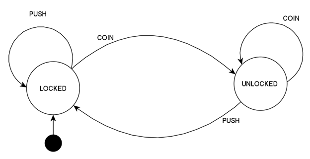 "Coin Acceptor Turnstile FSM". (Source Codeless Data Structures and Algorithms by Armstrong Subero).
We have a black dot which represents the initial state along with two states, locked and unlocked. The turnstile in a locked state will become unlocked once you insert a coin. Even if you push on the machine it will not unlock until you insert a coin. Once you insert a coin the machine enters into the unlocked state and will remain in that state as long as a coin a present.
If you push on the turnstile while in the unlocked state, that condition will cause the machine to transition into a locked state which it will remain in until a coin is entered again.
As simple as it seems, this method of modeling program tasks as states which transition based on conditions is a powerful method of embedded system firmware design. It is the method I use most often when designing my own systems.
Ventilators are Real Time Systems
Real Time Systems or RTS are systems which must meet strict requirements in terms of response times. In a real time system there is no room for compromise.
Such systems must guarantee that they will perform an action within a given time period. Failure to perform action within a certain time may lead to loss of life or serious damage to property.
This is the category of systems a ventilator falls into.
When a patient requires a ventilator, it is because they cannot breathe properly and need mechanical assistance to breathe required by a ventilator. A ventilator can perform Continuous Mandatory Ventilation (CMV) which means that the patient will be required to get a minimum number of breaths from the machine guaranteed.
Failure to provide the minimum number of breaths required will result in death of the patient. That means that the control electronics must be able to perform without failure.
To accomplish this most real time systems will utilize what is known as a real time operating system (RTOS) to ensure that the many tasks to be performed by the device can all be performed without fail.
RTOSs use a scheduler to manage tasks and limit how each task utilizes resources. The kernel would manage how each task can utilize the hardware resources based on their priority.
Think of the current makeshift ventilator designs that exist. The most promising ones are built using a bag-valve resuscitator that uses motors to actuate mechanical arms that press on the bag-value resuscitator and perform the ventilator functions.
However what will happen if the motor fails? Maybe we can add an infrared or ultrasonic sensor that will measure distance of the the mechanical arm from a certain point and ensure it reaches a particular distance. These sensors can also ensure that it returns to the starting point.
However the main microcontroller reading those sensors needs time to process the information. What if a sensor fails? Must the microcontroller lock up waiting for sensor data? Will a failure in sensor prevent the motor from being actuated on time?
To ensure each task takes place at a certain time, the scheduler will only allocate processing time to the task as designated by the system designer.
That way if a sensor fails, once the time allocated to reading that sensor has passed, the microcontroller will move on to the other task of actuating the motor which will keep the system running.
Using a Real Time Operating System in your design will guarantee that your device will be able to perform its function within the specified time.
Ventilators are Safety Critical Systems
In the previous section we discussed real time operating systems. I think we should expand our discussion a little and talk about hard real time vs soft real time systems.
In hard real time systems, the requirement of operation is that it MUST happen within the specified time at all costs, and failure to meet deadlines is not acceptable. Air traffic control systems and ventilator systems fall into this category.
Hard real time systems are not allowed to miss deadlines.
In soft real time systems, it is preferred that deadlines are met. But if deadlines are not always met it means that it may upset the end user but may be acceptable. Think of an online gaming platform. We would like to have real time response of our games, but if you miss a few frames it will not result in loss of life.
Soft real time systems are allowed to miss deadlines.
Now, a lot of people mistake a real time system with a safety critical system. Not all real time systems are safety critical systems. Think of the example above with online gaming or video conferencing – such systems require real time performance but they are not safety critical in nature.
What makes a safety critical system (SCS) different from a regular real time system is that failure to meet a deadline within a safety critical system will result in death or serious property loss.
In a safety critical system, stoppage of the system is NOT an option.
For example a high availability system real time system may be specified as having an up time of around 99% in a 24 hour period.
Think about a ventilator system.
Which 1% of the day is it acceptable to have the ventilator not operational? Since we have 1440 minutes in a day, which 14.4 minutes of the day should the patient not be allowed to breathe?
The Arduino Platform
At this stage in our discussion, I think it's best we talk about the Arduino platform for use in safety critical systems.
In our discussion of embedded systems, we talked about hardware and software, however did you know that there is also the development tools component of the design process?
You see, in order to put the software you have written into the microcontroller device running the hardware, you need to use development tools such as an IDE and toolchain to program the device.
Setting up and using a toolchain was a painful process depending on the device you were using. Many microcontroller vendors used to provide clunky IDEs that you had to be a seasoned embedded designer to use (though this has changed in recent years).
Additionally you also needed knowledge of the underlying hardware, and configuring registers and clocks can be daunting even for experienced designers.
Even if you overcame these hurdles on the software side, you needed to have a Printed Circuit Board (PCB) or have experience using a breadboard to get your microcontroller running.
It you did not know how to properly connect your hardware, even if your program was correct, the device would not run and troubleshooting the hardware also required some experience.
In order to address the problem, the Arduino platform was introduced as a way to provide synergy between hardware, software, and development tools to allow students control hardware with ease.
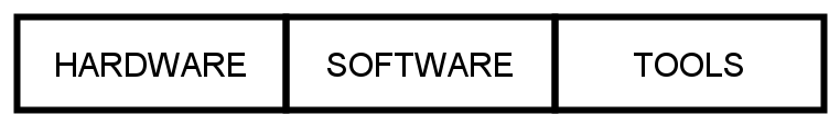 The Components of the Arduino Platform
The Arduino provides a physical board with the chip that is in a configuration known to work along with a simple IDE with tons of libraries. This seamless integration makes a less intimidating foray for beginners looking to get into the realm of hardware design.
The Problem with Using Arduino in Safety Critical Systems
There is one problem: since the Arduino is so easy to use, this has led many people to use the Arduino far beyond what the platform was originally intended for, including use in real time systems.
It's not recommended to use the Arduino for real time systems. Why? Some people may argue that you can use an operating system such as Amazon FreeRTOS on the Arduino and make it real time. That is true. But while the platform does become real time and it will make it highly reliable, it will not make it a safety critical one.
What makes the Arduino not suitable for use in safety critical systems? The answer lies in abstraction and its relation to the testing and debugging capability of the platform.
The Arduino is a good platform for learning, and as such it adds a lot of software abstraction to make things easy.
Abstraction in itself is not necessarily a bad thing. Abstraction allows for code reuse and can help eliminate bugs if used correctly. Properly tested code that abstracts away a lot of the hardware can be a powerful tool in the right hands.
However abstraction does NOT eliminate bugs and there is the problem. Even if code is abstract, if it had faulty logic to begin with then abstraction will not save you.
If you find a bug, usually you would rely on a debugger and software tests to help you figure out the source and improve the system reliability.
Therein lies the problem. The Arduino platform has no debugging capability.
Having no debugging makes bugs difficult to track. Having software that a bug free is crucial in a safety critical design. Additionally running tests on your code is not easy as the IDE is too simple for the powerful debugging and testing that is required for safety critical system design.
If you have no choice you can use the Arduino for design of a ventilator system. But the lack of debugging makes it difficult to do so and increases the likelihood of bugs in your firmware, and increases the risk of failure within the system.
How Can I Design a Good Makeshift System?
If you must design a ventilator system, there are two specific things you can do to improve your design based on the Arduino: You can improve the software design and improve the hardware design.
Improving Design on the Software Side
All hope is not lost. To make sure your system has reliable software consider doing the following:
- Consider using Another IDE - Atmel Studio is a great IDE that provides the option for debugging if you use an external debugger such as the Atmel ICE or ICD 4 debugger. Additionally MPLAB X can be used. These IDE's will assist with debugging.
- Adhere to a C/C++ coding standard - Using a code standard can improve your system reliability and make your system design more efficient. Consider rewriting the libraries you are using to adhere to MISRA, JSF++ or even the Barr Group's embedded C coding standard
- Use an RTOS - Many of the ventilator designs based on the Arduino utilize the platform as is with a cyclic execution system in place. Consider using the Amazon FreeRTOS to make your system real time. This would avoid system lockup and make your system more reliable.
- Consider using a Platform with Libraries that meet Safety Requirements – While not ideal for inexperienced designers, using a device that has libraries that already have existing safety requirements will help make your design more robust.
For example even though our device is a makeshift medical device, using IEC 60730 requirements for Class B safety can help make your design more robust. Microchip Technology (company that makes the chip that powers the Arduino) has other devices that has libraries that meet Class B safety requirements and would aid in improving device safety. - Implement Sensor Data Analytic Redundancy - When designing your device consider using sensors to ensure the device is still operational and when you do, consider using analytic redundancy methods to aid with more accurate sensor data.
- Consider using SAFERTOS - While it may require you to change systems SAFERTOS is pre-certified for use in medical systems and will provide a higher level of safety that the software of the Arduino platform.
Improving Design on the Hardware Side
To improve your design on the hardware side:
- Consider using a Watch Dog Timer - If you don't have time to use an RTOS, a simple way to ensure your device keeps operating is to use a watchdog timer in your design. The watchdog timer ensures the device resets if a problem occurs in the execution of your code.
- Use a Hardware Device with Pre-existing Safety Certifications and Libraries - Some devices are better suited for the task of a ventilator design. Rather than entrust a safety critical design to an Arduino, consider using a control device that can use software that is already certified for medical device use or provides safety libraries.
The SAFERTOS supported platforms is a good place to start. The Microchip Technology web page on Class B safety software is also a good place to start. - Add Feedback Systems - It is not enough to have your device up and running. You also need feedback systems to ensure devices are operating as they should. Integrate sensors to provide feedback on mechanical parts that are subject to failure.
- Consider Distributed Hardware Control- Though many persons base their designs on a single chip consider using multiple microcontrollers in your design. Consider having one device for control and another for notifying the end user if a component is failing.
- Implement System Redundancy - Having a proper shutdown system with a proper transfer system is crucial for such designs. Implement a proper shutdown procedure in case the system fails as well as have a proper switch over mechanism to ensure you have a 100% up time on your system.
Wrapping Up
In this post we looked at embedded systems, briefly talked about their hardware and software components, and touched on firmware design paradigms. We also talked about real time systems and safety critical systems as it relates to ventilator design.
Finally, we talked about how to improve the safety and reliably of your Arduino-based ventilator designs by improving the hardware and software design.
By the end of this post you should have some understanding of how to enhance your makeshift Arduino ventilator system.
If you wish to learn more about microcontrollers, pick up my book "Programming PIC Microcontrollers with XC8" where you will learn about the PIC microcontroller and how to program it. This microcontroller can also be used to design your ventilators and will give you a greater degree of control and debugging capability than the Arduino platform.
Read the book here: