
Arduino is an open-source platform that combines hardware and software in designing and building electronic projects.
Arduino can be applied in a variety of projects like:
- Home automation.
- Internet of Things (IoT).
- Audio and music.
- Automated and remote controlled systems.
- Automation in agriculture.
- Electronic prototyping.
- Wearable devices, and so much more.
The hardware part of Arduino comprises Arduino boards, input and output devices (including digital and analog pins, and sensors and actuators), shields, breadboards, jumper wires, and so on. These components can be combined together to create dynamic and interactive projects.
The software is made up of the development tools used to write, debug, compile, and upload code to Arduino boards. Most 0f the software tools can be found in the Arduino IDE (Integrated Development Environment).
This handbook will help you understand how Arduino works. You'll learn about the Arduino boards, the components that make up a board, and how to connect devices to them.
We'll talk about input and output peripherals which help the microcontroller (the brain of the Arduino board) process information coming from the physical environment, and send output based on programmed logic.
You'll learn about the Arduino IDE, how to code using the Arduino programming language, and how to use sensors, actuators, and other components to build projects as you learn.
You'll also learn about serial communication, which helps Arduino boards communicate with other computers.
This handbook is written for makers (students, artists, hobbyists, programmers) who are beginners.
Prerequisites
Although it would be helpful, you don't need prior programming knowledge to use this handbook. You will learn the basics of Arduino programming from scratch. This can also serve as your introduction to programming.
To make it beginner friendly, we won't talk about some aspects of electronics like current and voltage, resistance, circuits (series and parallel), and most basic electronic/electrical laws and requirements for students in STEM (Science, Technology, Engineering, Mathematics) fields.
Whether you have knowledge of these concepts or not, you can learn about Arduino using this handbook.
If you know how to use a breadboard and a resistor, then that's all the knowledge on electronics you'll need to follow along.
In summary, this handbook is for everyone. You don't need an engineering degree to become an Arduino maker!
Table of Contents:
- Prerequisites
- Chapter 1: Getting Started with Arduino
- Chapter 2: Basics of Arduino Programming
- Chapter 3: How to use Digital Pins in Arduino
- Chapter 4: How to use Analog Pins in Arduino
- Chapter 5: How to use Sensors and Actuators in Arduino
- Chapter 6: How to use the Serial Monitor in Arduino
- Chapter 7: How to use Displays in Arduino
Chapter 1: Getting Started with Arduino
The Arduino development and design process comprises both hardware and software. So knowing how they work together is important for building the right foundation for your journey.
In this chapter, you’ll learn about the different components that make up the Arduino Uno board. You'll also learn how to install the Arduino IDE and set up your development environment.
At the time of writing, a new Uno board was released — the Arduino Uno R4. This handbook will make use of the Uno R3 board, but you can follow along with either of them. The R4 board comes in two variants — Arduino Uno R4 WiFi and Arduino Uno R4 Minima — with cool additional features that you can read about here.
Components of the Arduino Uno R3 Board
There are many types of Arduino boards like Arduino Nano, Arduino Uno, Arduino Mega, Arduino Leonardo, and so on.
These boards have some common features — they all have digital and output pins, they’re programmable, and they all have a microcontroller.
But there are also some differences. Each board varies in size and shape, and usually has more or fewer components when compared to other boards.
The common boards you’ll come across as a beginner are the Nano, Uno, and Mega boards. The most commonly used is the Uno board, which we’ll use for this handbook.
Here are some of the components you'll find on the Uno R3 board:
- A power port.
- USB connector.
- Microcontroller (ATmega328).
- Analog pins.
- Digital pins.
- Reset button.
- TX and RX indicators.
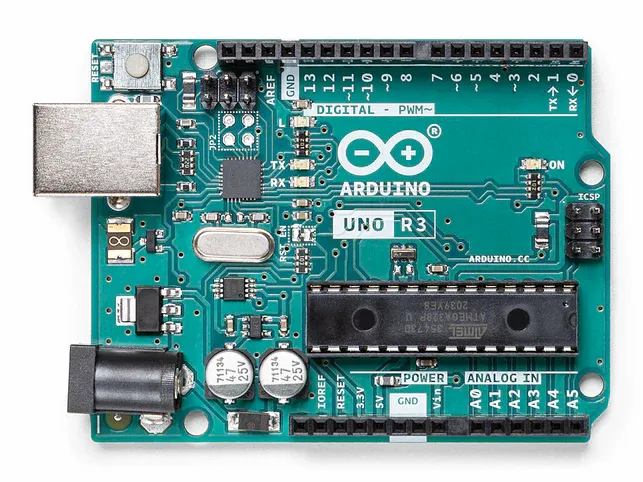 Arduino Uno R3 board (https://store.arduino.cc/products/arduino-uno-rev3)
You’ll make use of most of the components listed above as you progress through this handbook.
How to Install and Set Up the Arduino IDE
You can use the Arduino IDE to program Arduino boards. That is, you write the code in the IDE, then upload it to the board.
In this section, you’ll learn how to set up the IDE, and create your first Arduino program (also called an Arduino sketch).
You can download the latest version of the Arduino IDE on the Arduino software download page. You can download the IDE for different operating systems — Windows, MacOS, and Linux.
The installation process is similar for the operating systems listed above. Here’s how to install it on a Windows machine:
Step #1 – Download the Arduino IDE
The first step is to download the IDE from the Arduino software download page. You should see a section of the page similar to the image below:
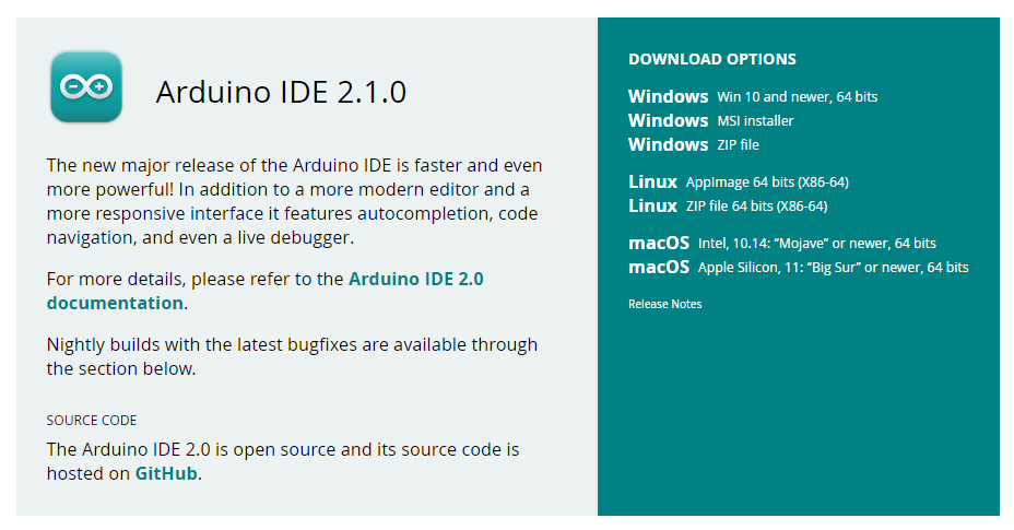
On the right side of the image above are different download options for specific operating systems. Make sure you download the option that suits your operating system.
I'll use the ZIP file option for Windows. If you decide to download an installer instead, then you can follow the installation steps after clicking the installation file.
Step #2 – Unzip the Downloaded File
Go on and unzip the downloaded file. This gives you access to all the resources needed to run the Arduino IDE.
After unzipping the file, you should see files like these:
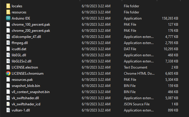 Image showing the files you should see
To launch the Arduino IDE, click on the file that says “Arduino IDE”.
Step #3 – Overview of the Arduino IDE
Now that you’ve downloaded and installed the Arduino IDE, the next part is to get familiar with the development environment. In the next section, you’ll learn how to upload code to an Arduino Uno board using the IDE.
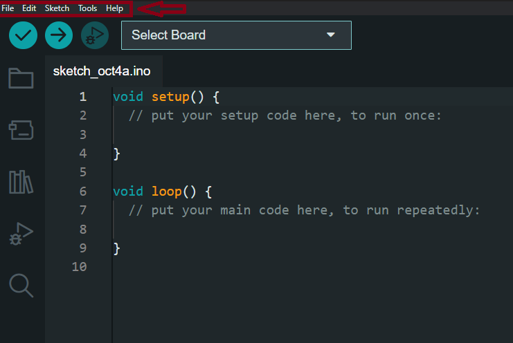
Before that, let’s have a look at some options you’ll find in the Arduino IDE. At the top left corner of the IDE are five options — File, Edit, Sketch, Tools, Help:
 Screenshot showing these options (File, Edit, Sketch, Tools, Help)
The “File” option lets you do different things like creating a new sketch (we’ll talk about sketches in the next section), opening an existing sketch, Arduino practice examples for beginners, keyboard shortcuts, save options, and so on.
The “Edit” option gives you access to text formatting options like copy, paste, cut, comment/uncomment code, font size options, text search options, and so on.
You can use the “Sketch” option to verify and compile code, upload code to Arduino boards, optimize code, and add libraries.
You can use the “Tools” option to manage libraries, format code, access the serial monitor and plotter, select an Arduino board and port to upload code to, choose a processor, and so on.
The “Help” option provides resources for troubleshooting, information on IDE updates, guides on “getting started”, and so on.
Next, let’s look at some other parts and functionalities in the IDE that you’ll find useful. The image below, from the Arduino documentation, highlights them perfectly:
![]() https://docs.arduino.cc/software/ide-v2/tutorials/getting-started-ide-v2
https://docs.arduino.cc/software/ide-v2/tutorials/getting-started-ide-v2
- Verify/Upload: You can use these options to compile and upload code to Arduino boards. You’ll get error messages if the code doesn't compile as expected.
- Select Board & Port: You can use this option to select a port and port number to upload your code too. The current version of the Arduino IDE automatically detects both boards and ports.
- Sketchbook: This gives you access to all the sketches created in your computer. You can also access sketches saved on Arduino Cloud (mostly used for creating IoT projects).
- Boards Manager: The Arduino IDE comes with support for different boards. As you progress through your journey, you’ll make use of different boards and some of them may not be supported by the IDE. The board manager tab lets you install and manage packages required to use these boards.
- Library Manager: You can use libraries to extend certain functionalities in code. Through the library manager, you can install numerous libraries that’ll help simplify the development process for you.
- Debugger: This is used for real time testing and debugging of Arduino programs.
- Search: You can use the search tool to find specific keywords in your code.
- Open Serial Monitor: You can use the serial monitor to communicate with Arduino boards, debug and test code, visualize data from your boards, interact with user input, and so on. We’ll look at the serial monitor in depth in a different chapter.
- Open Serial Plotter: The serial plotter is mostly used for real-time visualization of numerical data.
What Is an Arduino Sketch?
We mentioned the term “sketch” a couple of times in the last section, but what is it? A sketch is a program written with the Arduino programming language. It’s another way of referring to a code file written for Arduino projects.
The Arduino programming language is built upon the C/C++ language so they both share similar syntax and structure. You may come across resources that refer to Arduino code as “embedded C” or “embedded C++”.
How to Upload Code to an Arduino Board
To upload code to an Arduino board, you'll need both hardware and software. The hardware is the board which is the Uno board in our case, and the software is the Arduino sketch in the IDE.
Here are the steps:
Step #1 – Connect the Arduino Board
Connect the Arduino board to your computer using the USB cable. Without this step, you can't go further.
Step #2 – Create a Sketch
Now it's time to launch the IDE and write some code.
Here's a code example that makes an LED blink:
int ledPin = 13;

void setup() {
  pinMode(ledPin, OUTPUT);
}

void loop() {
  digitalWrite(ledPin, HIGH);
  delay(1000);
  digitalWrite(ledPin, LOW);
  delay(1000);
}
Don't worry if you don't understand the code — we'll cover everything as we go further.
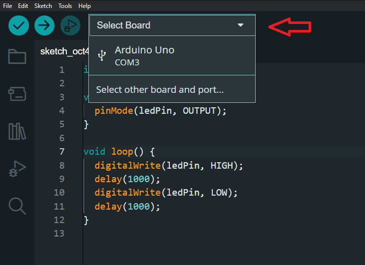
Step #3 – Select the Board and Port
You can select the board to upload your code to from the IDE. Here's an image showing what that looks like:
Step #4 – Verify the Code
You can use the verify button to compile the code and check for errors. If errors exist, you'll get an error message to show you the possible cause.
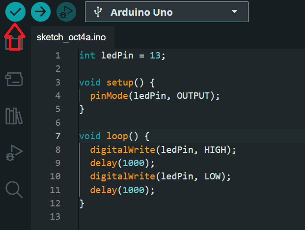 Image showing the verify button
Step #5 – Upload the Code
You can upload the code using the upload button (the button after the verify button).
If there are no errors in your code, these steps will help upload code to your board. If you've uploaded the code above, you should have the built-in LED (it is connected to pin 13 by design) on the Uno board blinking.
In the next chapter, you'll learn the basics of the Arduino programming language.
Chapter 2: Basics of Arduino Programming
Before we dive into creating our own sketches and tinkering, you have to understand the logic that make these boards work as expected. To do that, you’ll have to know how to code using the Arduino programming language.
As discussed in the last chapter, the Arduino language is built upon C/C++. You’ll begin this chapter by learning the basics of programming. This will prepare you for every other chapter that involves writing code.
I’ve created this chapter with beginners in mind. If you’ve never written code before then this can serve as a starting point for you. This doesn’t mean you’ll learn how to code in C or C++. You’ll be learning how to write Arduino code which shares similar syntax with those languages.
At the end of this chapter, you should be able to understand and write Arduino code.
Variables and Data Types in Arduino
Variables and data types are used in most programming languages to store and manipulate data. You can think of variables as containers or storage units. Data types, like the name implies, are the type of data stored in variables.
In Arduino programming, you must specify the data type of a variable before using it. That is:
dataType variableName = variableValue
There are different types of data types in Arduino, and we’ll discuss each one along with code examples.
int Data Type in Arduino
The int data type is used to store integer values. The Uno board has a 16-bit integer capacity so it can store values that fall within the range of -32,768 to 32,767.
int redLED = 6;
In the code above, we created an integer variable called redLED with a value of 6.
The int data type can also store negative integers:
int redLED = -6;
long Data Type in Arduino
The long data type is similar to int but has a wider range of integer values. It has a 32-bit integer limit which falls within the range of -2,147,483,648 to 2,147,483,647.
long largeNumber = 6000;
float Data Type in Arduino
The float data type can be used to store numbers with decimals. Float variables can store values up to 3.4028235E+38 and values as low as -3.4028235E+38.
float num = 10.5;
Although the float data type is mainly used for decimal numbers, it can also accept whole numbers (integers without decimals). But it'll always return a float value. So if you store 10 in a float, it'll return 10.00.
String Data Type in Arduino
You can use the String data type to store and manipulate text. You'll work with strings occasionally to display information in the form of text when building projects.
Here's a code example:
String greeting = "Hello World!";
The value of strings are nested within double quotation marks as can be seen in the code above.
Note that when declaring a string, the "S" should always be in uppercase.
char Data Type in Arduino
The char data type stores single characters.
Here's an example:
char alphabet = 'A';
This is different from the String data type that can store multiple characters.
There are two main differences between char and String:
charuses single quotes ('A') whilestringuses double quotes ("Arduino").charstores single characters whilestringstores multiple characters.
char can also accept integer values equivalent to the ASCII value of letters:
char charValue = 65;
In the code above, we initialized a char variable with the value of 65. When printed to the serial monitor (we'll talk about the serial monitor in Chapter 6: How to use the Serial Monitor in Arduino), A will be returned.
A is returned because 65 has an ASCII character of A.
bool and boolean Data Types in Arduino
You can use both bool and boolean to store/denote boolean values of either true or false.
bool roomIsCold = false;
Boolean values are mostly used with logical and comparison operators, and conditional statements (you'll learn about these later in this chapter) to manipulate and control different outcomes in an Arduino program.
byte Data Type in Arduino
The byte data type has an 8-bit unsigned integer limit that ranges from 0 to 255. Unsigned means that it can't store negative values.
byte sensorValue = 200;
The byte data type isn't the only data type that can be unsigned. You can also use the unsigned int, unsigned long, and unsigned char data types which all have their respective positive integer ranges.
Operators in Arduino
Operators are symbols or characters that can be used to perform certain operations on operands. An operand is simply any value(s) an operator acts on.
There are different categories of operators in Arduino like:
Arithmetic Operators
Arithmetic operators are used to perform mathematical operations like addition, subtraction, division, multiplication, and so on. Here are some arithmetic operators you should know:
Addition(+) Operator
The addition operator, denoted by the + symbol, adds two operands together:
int a = 5;
int b = 10;

// we use addition operator to add a and b below
int c = a + b;

Serial.print(c);
// 15
Subtraction(-) Operator
The subtraction operator subtracts the value of one operand from another operand. It is denoted by the - symbol:
int a = 5;
int b = 10;

// we use subtraction operator to subtract b from a below
int c = b - a;

Serial.print(c);
// 5
Multiplication (*) Operator
You can use the multiplication operator (*) to multiply two operands:
int a = 5;
int b = 10;

// we use multiplication operator to multiply a by b below
int c = a * b;

Serial.print(c);
// 50
Division(/) Operator
The division operator divides one operand by another:
int a = 5;
int b = 10;

// we use division operator to divide b by a below
int c = b / a;

Serial.print(c);
// 2
Modulus (%) Operator
The modulus operator returns the remainder of a division between two operands:
int a = 5;
int b = 10;

// we use division operator to divide b by a below
int c = b % a;

Serial.print(c);
// 0
Increment (++) Operator
The increment operator increases the value of a variable by 1:
int num = 5;
num++;

Serial.print(num);
// 6
Decrement (--) Operator
The decrement operator decreases the value of a variable by 1:
int num = 5;
num--;

Serial.print(num);
// 4
Assignment Operators
Assignment operators are mainly used to assign values to variables. You can also use them to update the value of variables.
The assignment (=) operator is used for assigning and updating variables. The = operator should not be confused for "equal to" — they aren't the same. We'll talk about the equal to (==) operator in the Comparison Operators section.
Here's an example that shows how to use the assignment operator:
int age = 1;
In the code above, we created a variable called age, and then assigned a value of 1 to it using the = operator.
But this isn't the only way to assign or update the value of variables when using the = operator. You can also use compound assignment operators.
Compound Assignment Operators
Compound assignment operators let you combine arithmetic operators and the = operator. This method provides a shorter way of writing code. Here is an example:
int x = 5;
x += 5;

Serial.print(x)
// 10
In the code above, we created an x variable and assigned a value of 5 to it. But on the second line, you'd see that we combined the arithmetic addition (+) operator and the = operator to assign a new value to x:
x += 5;
The line of code above is the same as this:
x = x + 5;
So compound operators combine two operators and let you do the same thing in a shorter way. There's nothing wrong with either method.
Here are other compound operator examples:
int a = 10;
a -= 5; // Equivalent to a = a - 5 (a becomes 5)

int b = 10;
b *= 5; // Equivalent to b = b * 5 (b becomes 50)

int c = 10;
c /= 5; // Equivalent to c = c / 5 (c becomes 2)

int d = 10;
d %= 5; // Equivalent to d = d % 3 (d becomes 0)
Comparison Operators
You can use comparison operators to compare two values/operands. Comparison operators return either true (1) or false (0) depending on the relationship between operands.
Comparison operators can help you make decisions based on their return values. You'll see them a lot when we start building projects.
Here are the comparison operators you'll come across occasionally:
Equal To (==) Operator
This operator compares the values of two variables. If the values are the same, it returns true. If the values are not the same, it returns false. Here's an example:
int x = 10;
int y = 5;

Serial.print(x == y)
// returns 0
The return value of x == y in the code above is 0 (false) because the two variables are not the same. Remember that the == operator returns 1 (true) only when both variables have the same value.
Not Equal (!=) Operator
The not equal operator checks whether two values have different values. It's does the opposite of the == operator. That means it'll return 1 (true) if both values are not of the same value and 0 (false) if both values are the same.
Here's an example:
int x = 10;
int y = 5;

Serial.print(x != y)
// returns 1
Greater Than (>) Operator
The greater than (>) operator checks if the operand on the left is greater than the operand on the right. If the left operand is greater, it returns 1. If the left operand is smaller, it returns 0.
int x = 10;
int y = 5;

Serial.print(x > y)
// returns 1
Less Than (<) Operator
The less than (<) operator checks if the operand on the left is less than the operand on the left. If the left operand is smaller, it returns 1. If the left operand is greater, it returns 0.
int x = 10;
int y = 5;

Serial.print(x < y)
// returns 0
Greater Than or Equal To (>=) Operator
Just like the name, the >= operator checks if the operand on the left is either greater than or equal to the operand on the right. It returns 1 if the left operand is greater than or equal to the right operand, and 0 if it isn't.
"Or" implies that either of the conditions can be used. If the left operand is not greater than the right operand but is equal to the right operand, you'll still get a value of 1.
int x = 10;
int y = 5;

Serial.print(x >= y)
// returns 1
Less Than or Equal To (<=) Operator
The <= operator checks if the left operand is either less than or equal to the right operand. If the left operand is less than or equal to the right operand, it returns 1, and returns 0 if the left operand is neither less than nor equal to the right operand.
int x = 10;
int y = 5;

Serial.print(x <= y)
// returns 0
Logical Operators
Logical operators are used in most programming languages to evaluate and determine the relationship between variables.
Here are the three logical operators you should know for Arduino programming:
Logical AND (&&) Operator
The logical AND (&&) operator returns 1 if both statements are true.
int x = 10;

Serial.print((x > 5) && (x > 3));
// returns 1
The expression above — (x > 5) && (x > 3) — returns 1 because both statements are true. That is, x > 3 and x > 3. If either or both of those statements were false, then we'd have a return value of 0.
Logical OR (||) Operator
The logical OR (||) operator returns 1 if one of both statements is true.
int x = 10;

Serial.print((x > 5) && (x > 15));
// returns 1
The code above returns 1 although one of the statements is false. This is because the || operator returns 1 if either or both statements are true.
Logical NOT (!) Operator
The NOT (!) operator negates or reverses the value of its operand. If the operand statement is true, it returns false, and returns false if the operand is true.
Here's an example:
int x = 10;

Serial.print(!(x > 5));
// returns 0
The code above returns 0, but why? x > 5 is true so the expected result is 1.
We got 0 because the ! operator reversed the return value of the operand from 0 to 1.
Conditional Statements in Arduino
You can use conditional statements to make decisions or execute code based on specific conditions. You can combine conditional statements and logic (like operators in the last section) to control how code is executed.
Let's take a look at some conditional statements and how to use them:
if Statement
The if statement is used to execute code if a condition is true. Here's what the syntax looks like:
if (condition) {
    // code to be executed if condition is true
}
In the syntax above, condition denotes a specified logic. If the condition is true then the code in the curly brackets will be executed. Here's an example:
int x = 5;
if (x < 10) {
  Serial.print("x is less than 10");
}

// x is less than 10
In the code above, we gave a condition— x < 10 — and a block of code within curly brackets that prints "x is less than 10". The code in the curly brackets will only run if the condition is true.
This is the same as saying "if x is less than 10 then print 'x is less than 10' to the serial monitor". Since x is less than 10, the condition evaluates as true and we get the message printed out.
But what if the condition is false? The code in the curly brackets won't run, so we'll need a different type of logic to handle situations like that. We can do this using the else statement.
else Statement
The else statement is used to execute code if a condition is false.
int score = 20;
if (score > 50 ) {
  Serial.print("You passed the exam!");
} else {
  Serial.print("You have to rewrite the exam!");
}

// You have to rewrite the exam
In the code above, the condition given is false. So the code for the else statement will be executed because the score variable is not greater than 50.
Remember: the code for the else statement only runs when the condition is false. If the condition is true then the code for the if statement will be executed.
else if Statement
You can use the else if statement to define multiple conditions to be checked. Here's the syntax:
if (condition1) {
    // code to be executed if condition1 is true
} else if (condition2){
    // code to be executed if condition2 is true
} else {
    // code to be executed if condition1 and condition2 are false
}
In the syntax above, there are two conditions (you can create more than two conditions). If condition1 is true, then code in the curly bracket for condition1 will be executed.
If condition1 is false, then condition2 will be evaluated. If condition2 is true, its block of code will be executed.
If both condition1 and condition2 are false, the else statement's code will be executed.
int score = 80;
if (score > 50 ) {
  Serial.print("You passed the exam!");
} else if (score < 50) {
  Serial.print("You have to rewrite the exam!");
} else {
  Serial.print("No records for your exam score found!");
}

// You passed the exam!
switch-case Statement
In the last section, we saw how to create multiple conditions using else if statements. Your code might become hard to read if you have many conditions. We can clean it up and make the code more readable using switch statements.
Here's what the syntax looks like:
switch (expression) {
    case 1:
        // Code to be executed if expression equals case 1
        break;
    case 2:
        // Code to be executed if expression equals case 2
        break;
     case 3:
        // Code to be executed if expression equals case 3
        break;
    default:
        // Code to be executed if expression doesn't match any case
        break;
}
Let's break the syntax down:
- The
expressionis compared to the value of eachcase. - When a
casematches theexpression, the code for that case is executed. - The
breakkeyword stops theswitchstatement's iteration once a match for theexpressionhas been found. - The code for the
defaultkeyword is executed if none of the cases match theexpression.
Here's an example:
int day = 2;

switch (day) {
  case 1:
    Serial.print("Monday");
    break;
  case 2:
    Serial.print("Tuesday");
    break;
  case 3:
    Serial.print("Wednesday");
    break;
  case 4:
    Serial.print("Thursday");
    break;
  case 5:
    Serial.print("Friday");
    break;
  case 6:
    Serial.print("Saturday");
    break;
  case 7:
    Serial.print("Sunday");
    break;
  default:
    Serial.print("Number out of range");
  }

//  Tuesday
The code above prints "Tuesday" because the expression which has a value of 2 matches case 2.
Loops in Arduino
You can use loops to execute code repeatedly until a certain condition is met. You can also use loops to iterate over a collection of data and execute code on all elements of the collection.
There are different type of loops you can use in Arduino like the for loop, while loop, and do-while loop. Let's take a look at their syntax along with some practical examples:
for loop
You can use the for loop to iterate through a collection or execute code until a certain condition is met. It is commonly used when you know the number of times the loop is supposed to run.
Here's the syntax:
for (initialization; condition; increment/decrement) {
   // code to be executed
}
There are three important keywords in the syntax above:
- initialization denotes an initial variable (usually an integer) which specifies the starting point of the loop.
- condition is used to control the number of times the loop is expected to run for. The loop stops when the condition is
false. - increment/decrement increases/decreases the value of the initial variable after every iteration.
Here's an example to help you understand the keywords:
for (int i = 0; i < 11; i++){
  Serial.println(i);
}

// 0
// 1
// 2
// 3
// 4
// 5
// 6
// 7
// 8
// 9
// 10
In the loop above, we created an initial variable called 1 with a value of 0.
The condition stated i < 11 which implies that the loop will continue to run as long as i is less than 11.
Using the increment operator i++, we increased the value of i by 1 every time the loop ran.
Lastly, we printed the value of i at every iteration. In the serial monitor, you'll notice the numbers from 0 to 10 printed out. This is because after the number 10, i is no longer less than 11 (the condition given), so the loop terminates.
while loop
The while loop works just like the for loop — it executes code as long as the given condition is true. But its often used when the number of times the loop is supposed to run is unknown.
Here's the syntax:
while (condition) {
    // Code to be executed
}
In the syntax above, the code will continue to run until the condition becomes false.
while (i < 11) {
  Serial.println(i);
  i++;
}

// 0
// 1
// 2
// 3
// 4
// 5
// 6
// 7
// 8
// 9
// 10
do-while Loop
The do-while loop is just like the while loop, but it executes its code block first before checking the validity of the condition given. That is, at the beginning of the loop, the code in curly brackets will run first even if the condition is false. After that, it starts checking if the condition is true or false, just like a normal loop.
In summary, the code for a do-while loop will run at least once, irrespective of the condition given. Here's an example:
do {
  // code block to be executed
}
while (condition);
Here's the code example:
int i = 0;

do {
  Serial.println(i);
  i++;
} while ( i < 11);

// 0
// 1
// 2
// 3
// 4
// 5
// 6
// 7
// 8
// 9
// 10
Arrays in Arduino
You can use arrays in Arduino to store multiple variables of the same data type in a single variable. Each element stored in an array can be accessed using its index number.
Array Declaration
Declaring an array simply means to create one. You can do that in Arduino using the syntax below:
dataType arrayName[arraySize]
In the syntax above:
dataTyperepresents the data types that'll be stored in the array. For instance, if the data type isint, then only integers can be stored in the array.arrayNamedenotes the name of the array.arraySizedenotes the number of elements that can be stored in the array.
Here's an array declaration code example:
int ages[4];
In the code above, we created an array called ages. The array can only store four elements with an int data type.
Array Initialization
To initialize an array means to assign values to the array. In the last section, we created an array called ages. Now, let's assign some elements to it:
int ages[4] = {2, 4, 6, 8};
You can see from the example above that there are only four elements in the array — 2, 4, 6, 8. Assigning a fifth element would throw an error because we specified that the array can only have for integer elements: int ages[4];.
You can access the elements of the array using their index number. Indexes start at zero (0) – so the first element has an index of 0, the second element has an index of 1, the third element has an index of 2, and so on.
int ages[4] = {2, 4, 6, 8};

Serial.print(ages[0]);
// 2
As can be seen above, we accessed the first element using the array name and the index of the element in square brackets: ages[0].
You can also assign and reassign values to a particular element using its index:
ages[0] = 10;
Note that you can declare and initialize an array at the same time. I only divided them into separate sections to help you understand what each term means.
Functions in Arduino
In the last chapter, we discussed some built-in functions in Arduino that can be used to carry out a variety of tasks related to Arduino hardware and software components. All we did was write the function name and pass in parameters where necessary and we got the desired outcome.
For instance, the digitalWrite() function writes values to digital pins using two parameters (the pin number and the value to be sent to the pin). Under the hood, some code logic handles that operation.
Let's assume that the logic required to send values to digital pins was up to a hundred lines of code. Without functions, you'll have to write those hundred lines every time you wanted to send values to digital pins.
Functions prevent you from having to reinvent the wheel. They also help you break your code down into smaller, more readable and manageable parts.
Just like how built-in functions can be reused to perform a particular task repeatedly, you can also create your own functions for specific functionalities, and that's exactly what you'll learn in this chapter.
How to Declare Functions in Arduino
There are four main parts of a function in Arduino:
- The type of data the function returns.
- The name of the function.
- The function parameter(s) which is optional.
- The body of the function.
Here's what that looks like:
dataType functionName(optionalParameters) {
    // body of the function
}
So from the syntax above, dataType is the data type the function returns. It can be int, String, and so on. A function that has no return statement uses the void type as its data type.
The functionName is the name given to the function. The name is used to call the function to execute the logic defined in the body of the function. You'd see words like "call", "fire", and "invoke" associated with functions. They all mean the same thing — to execute the function's logic.
optionalParameters are variables that you define when creating a function. They enable functions to accept external data which can be used within the function body. Function parameters are defined along with their data types. You'll understand this when we look at some examples.
The body of the function is where all the logic goes to. What the function does when it is invoked is written in the body.
Now that we've seen the different parts of a function, let's create some functions!
How to Declare a Function with the void Type
In the last chapter, we discussed the void Setup() and void loop() functions. They are two built-in functions that you'll use in every Arduino sketch. These functions are defined using the void keyword because they return nothing
Here's what the syntax looks like for functions that use the void type:
void functionName(optionalParameters) {
    // code logic
}
In the syntax above, functionName denotes the name of the function. We can use that name to call the function in order to execute the code defined in the function.
optionalParameters are used to pass external data to the function while the code logic that runs when the function is called is written between the curly brackets.
Here's an example:
// function declaration
void printName(String userName) {
  Serial.println("Hello " + userName);
}

void setup() {
  Serial.begin(9600);
}

void loop() {
  printName("Ihechikara"); // function call
  delay(1000);
}
In the code above, we created a function called printName which accepts a string parameter called userName. The function's task is to print "Hello " along with whatever the parameter value is.
In the void loop(), we called the function and passed a parameter to it: printName("Ihechikara"). In the serial monitor, you'll see "Hello Ihechikara" printed.
To call a function, all you have to do is write the name of the function with parenthesis: printName(). Remember to pass in parameters when required: printName("Ihechikara").
Using a parameter that has the wrong data type will result in an error. For instance, we defined a string parameter in our example. Using an integer will raise an error because the function expects a string.
How to Declare a Function with a Return Data Type
In this section, I'll use the int data type to show you how functions declared without the void type are used. The logic here is the same with other functions that use the return statement.
// function declaration
int addNums(int a, int b) {

  int result = a + b;
  return result;
}

void setup() {
  Serial.begin(9600);
}

void loop() {
  Serial.println(addNums(2, 10)); // function call
  delay(1000);
}
In the code above, we declared a function with the int type: int addNums(int a, int b) {...}. This implies that the function is expected to return an integer value.
The function's logic adds the value of the two parameters (a and b) and returns their sum. We used the return statement to return the sum of the parameters.
We can now say that the task of the addNums function is to return the sum of two given parameters. This can be seen when we used the function in the void loop():
Serial.println(addNums(2, 10));
We called the function with two parameters and got their sum printed out in the serial monitor.
What You Should Know About the return Statement
In the last two sections, we saw how to use functions in two different ways — functions that use the return statement and functions that don't use it.
But what if you used the return statement in a void function? Would that break the code? The answer is no. I'll explain why.
The main use of the return keyword is to return a value from the function, and then terminate the function. Consider the example below:
int addNums(int a, int b) {

  int result = a + b;
  Serial.println(result);
  return result;

  // This part will be ignored
  Serial.println("Hello World");
}
The function above takes in two parameters — a and b — and returns their sum. You'll notice that we printed "Hello World" after the return statement. The part of the code that comes after the return statement will not be executed because the function terminates/stops its operation once it sees a return statement.
So you should always remember that anything that comes after the return statement will be ignored.
You can use the return statement in void functions but it is a convention not to. We simply use the void keyword to define functions that have no use for the return statement.
Commonly Used Built-in Functions in Arduino Sketch
In this section, we’ll discuss some of the commonly used built-in functions you’ll come across when writing or reading Arduino code. We'll make use of them in most of the upcoming chapters of this handbook.
We'll begin with the two main parts of an Arduino sketch — the setup() and loop() functions.
setup() and loop() Functions in Arduino
You can use the setup() function to configure analog and digital pins, initialize variables, and do other setup functionalities. The setup() function is executed once — when the board is powered on or reset.
The loop() function runs continuously. This part of the sketch is where you write all the code logic. You can use the loop() function to give the Arduino board instructions on different components and sensors.
void setup() {
  // put your setup code here, to run once:

}

void loop() {
  // put your main code here, to run repeatedly:

}
pinMode() Function in Arduino
The pinMode() function is used to configure pins as input or output pins. It can also be used to configure a resistor to act as either a pull-up or pull-down resistor. You'll understand more about this function in the Sensors and Actuators chapter.
Syntax
pinMode(pin, mode)
pindenotes the pin number on an Arduino board.modedenotes the configuration of thepinwhich can be INPUT, OUTPUT, or INPUT_PULLUP.
digitalRead() Function in Arduino
You can use the digitalRead() function to read the state of digital pins. It returns either 0 (LOW) or 1 (HIGH).
Syntax
digitalRead(pin)
In the code above, pin denotes the pin number on an Arduino board.
digitalWrite() Function in Arduino
The digitalWrite() function assigns or writes values (either HIGH or LOW) to digital pins.
Syntax
digitalWrite(pin, value)
pindenotes the pin number on an Arduino board.valuedenotes the value to be assigned topin. Can beHIGHorLOW.
analogRead() Function in Arduino
The analogRead() function reads values from analog pins and returns values that fall within the range of 0 and 1023.
Syntax
analogRead(pin)
In the code above, pin denotes the pin number on an Arduino board.
analogWrite() Function in Arduino
This function writes or assigns an analog value to a pin.
Syntax
analogWrite(pin, value)
pindenotes the pin number on an Arduino board.valuedenotes the value to be assigned topin. Range from 0 to 255.
Serial Functions in Arduino
Serial communication enables an Arduino board to communicate with the computer and other devices using the built-in serial monitor. Here are some of the commonly used functions:
Serial.begin()
The Serial.begin() function initializes serial communication. It is the first function you use when working with the serial monitor. The function takes in a baud rate as its parameter.
In this case, baud rate represents the rate or speed of data transfer in serial communication.
Here's the syntax:
Serial.begin(baudRate)
Serial.print() and Serial.println()
You can use the print() and println() functions to print data to the serial monitor.
print(val)
println(val)
In the code above, val denotes the value to be printed.
We'll talk more about serial communication in Chapter 6: How to use the Serial Monitor in Arduino.
delay() Function in Arduino
You can use the delay() function to pause the Arduino program for a specified amount of time. Here's what the syntax looks like:
delay(ms)
In the code above, ms denotes the specified time in milliseconds.
Chapter 3: How to Use Digital Pins in Arduino
Digital pins are used to send and receive digital signals in two states — HIGH and LOW. The digital pins on a Arduino board can be configured as either input or output pins.
These states can also be represented using numbers (1 for HIGH and 0 for LOW), or in volts (V) (5V for HIGH and 0V for LOW).
The number and arrangement of pins differ in various Arduino boards, but they serve the same purpose. So if you understand how to use them in this chapter, you won't have a problem working with them in other boards.
The Uno board has 14 digital pins numbered from 0 to 13. Although each pin can be configured to serve as either a digital input or output pin, some of them come with extra functionalities like:
- Pins 0 (RX) and 1 (TX) enable the Arduino board to communicate serially. RX receives while TX sends.
- Pins that have the tilde (~) symbol beside them support PWM (Pulse Width Modulation) signals. This means that you can use these pins like analog pins (to receive analog values).
- Pins 2 and 3 can be used for interrupt-based functionalities.
How to Configure Digital Pins as Input or Output Pins
When a digital pin is configured as an INPUT pin, it serves as a point for receiving information from components. This way you get data from sensors, electronic components, and so on.
You can use the pinMode() function to configure a pin to serve as either an INPUT or OUTPUT pin. Note that the pins on an Uno board are set to INPUT by default so if you don't specify prior to using them, they'll serve as input pins.
In this section, you'll learn how to use digital pins as both input and output pins. You'll start by learning about them individually, and then see how to combine input and output signals to build a mini project.
We'll start with INPUT.
Digital Pins as INPUT
The information or signal sent to input pins can be read using the digitalRead() function. In this section, you'll learn how to configure and read signals from a digital input pin using different built-in functions.
We'll use the following hardware components:
- Arduino Uno.
- Breadboard.
- Pushbutton.
- Jumper wires.
Here's the diagram for the connection:
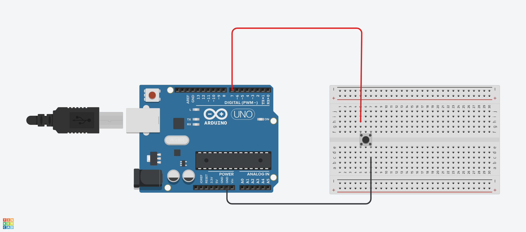 Configuration diagram – INPUT
Here's the code:
int pushBtn = 7;
int push_btn_state;

void setup(){
  pinMode(pushBtn, INPUT_PULLUP);
  Serial.begin(9600);
}

void loop(){
  push_btn_state = digitalRead(pushBtn);
  Serial.println(push_btn_state);
  delay(1000);
}
Let's break the code down.
We started by creating two integer variables — pushBtn and push_btn_state:
int pushBtn = 7;
int push_btn_state;
pushBtn was assigned a value of 7. We used this value to denote pin 7 on the Arduino board. We declared the push_btn_state variable but didn't assign any value to it because we'll use it to store the value of the push button later.
In our setup() function, we configured the push button to act as an input pin using the pinMode() function:
pinMode(pushBtn, INPUT_PULLUP);
The function took in two parameters — the pushBtn variable which denoted pin 7, and INPUT_PULLUP which sets the pin as an input with a pull-up resistor.
We also initialized the serial monitor using Serial.begin(9600).
At this point, we've configured the Arduino software and hardware to recognize pin 7 as an input pin.
Next, we used the digitalRead() function to read signals coming from pin 7. Remember the push_btn_state variable we created? That's where we stored the signal:
push_btn_state = digitalRead(pushBtn);
After that, we printed the value being read from pin 7 to the serial monitor using Serial.println(push_btn_state);.
When you open the serial monitor, you'll see 1 being printed out repeatedly. This is the initial state of the pushbutton using a pull-up resistor. When you press down the pushbutton, the value will become 0. When you release the button, the value will become 1.
0 denotes LOW while 1 denotes HIGH. With this example, you should understand how to configure, read, and display signals from an input pin.
Digital Pins as OUTPUT
The main use of an output pin is to send out signals. Since we're working with digital output, we can send either HIGH (5V) or LOW (0V) signals. We can do this for digital pins using the digitalWrite() function.
In this section, we'll use a LED (Light Emitting Diode) to demonstrate how to configure and send signals to components.
Here are the components we'll use:
- Arduino Uno.
- Red LED.
- 1k Ohm resistor.
- Jumper wires.
- Breadboard.
Here's the circuit diagram:
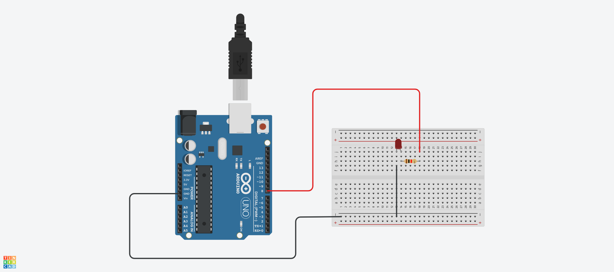 Configuration diagram – OUTPUT
int RedLED = 8;

void setup(){
  pinMode(RedLED, OUTPUT);
}

void loop(){
  digitalWrite(RedLED, HIGH);
  delay(1000);
  digitalWrite(RedLED, LOW);
  delay(1000);
}
In the code above, we configured the red LED, which is connected to pin 8 on the Uno board, as an output pin using the pinMode() function.
We then used the digitalWrite() function to send signals to the pin:
  digitalWrite(RedLED, HIGH);
  delay(1000);
  digitalWrite(RedLED, LOW);
  delay(1000);
With the HIGH parameter, we send 5V to the pin which makes the LED come on. With LOW, we send 0V which turns the LED off. So the LED comes on and off continuously with a delay of 1000 milliseconds. This example is commonly known as the "BLINK" example.
Digital I/O Project
Now that we've understood how to send and receive digital signals using Arduino, let's combine both of them to build an interactive project.
The idea is to control an LED using a pushbutton. When you press the button, the LED goes off, and comes back on when you release the button.
We'll combine the components used in the previous examples:
- Arduino Uno.
- Red LED.
- 1k Ohm resistor.
- Pushbutton.
- Jumper wires.
- Breadboard.
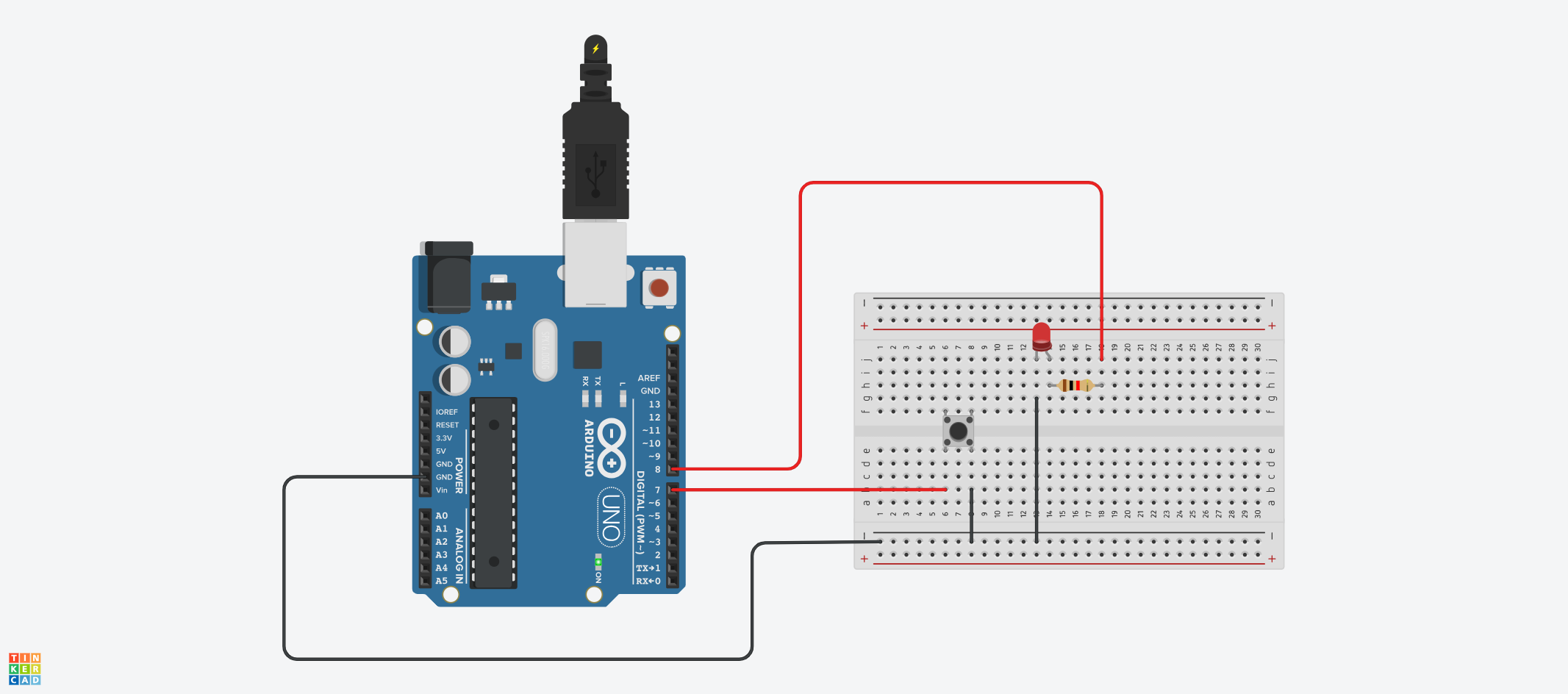 Configuration diagram - INPUT and OUTPUT project
Here's the code:
int pushBtn = 7;
int push_btn_state;
int RedLED = 8;

void setup(){
  pinMode(pushBtn, INPUT_PULLUP);
  pinMode(RedLED, OUTPUT);
}

void loop(){
  push_btn_state = digitalRead(pushBtn);

  if (push_btn_state == 1) {
    digitalWrite(RedLED, HIGH);
  } else {
    digitalWrite(RedLED, LOW);
  }
}
Here's a breakdown of the code above:
First, we connected the pushbutton to pin 7 and the red LED to pin 8.
Then we configured both pins — pin 7 as input, and pin 8 as output.
Next, we read the value of the pushbutton using the digitalRead() function and stored the value in a variable called push_btn_state.
Using an if statement, we checked for the state of the pushbutton. When push_btn_state is not being pushed down, it has a value of 1 (HIGH). We send 5V to the LED using digitalWrite().
When push_btn_state is pushed down, it has a value of 0, and we send 0V to the LED which turns it off.
Chapter 4: How to Use Analog Pins in Arduino
Analog pins can be used to receive and send voltage values from/to different sensors and components. Unlike digital signals that fall within two states of 0 (LOW) and 1 (HIGH), analog values have a wider range of values from 0 to 1023.
The Uno board has six analog pins — A0, A1, A2, A3, A4, and A5. These pins are INPUT pins by default.
Similar to digital pins, there are in-built functions for receiving and sending analog voltage signals. You can use the analogRead() function to read/receive analog values from pins while the analogWrite() function can be used to write to specific pins.
Note that the analogWrite() function doesn't write or send analog values to analog pins. It sends analog voltage values (that get converted to digital signals) to digital pins that support PWM (Pulse Width Modulation).
You can find PWM digital pins on the Arduino board by the (~) symbol beside them. On the Uno board, there are pins 3, 5, 6, 9, 10, and 11.
In the project for this section, you'll learn how to adjust the brightness of an LED using a potentiometer. We'll use the potentiometer as an input component, and send its voltage to an LED to increase/decrease the LED's brightness.
Here are the components we'll use:
- Arduino Uno.
- Yellow LED.
- Potentiometer.
- 1k Ohm resistor.
- Jumper wires.
- Breadboard.
Here's the circuit diagram:
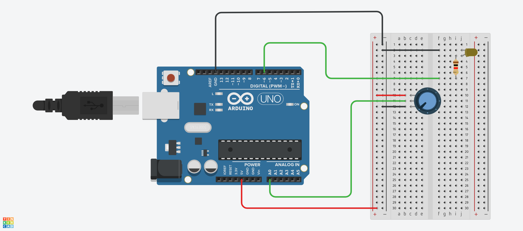 Configuration diagram
Here's the code for the circuit:
int potentiometer = A0;
int pot_value = 0;
float pot_in_PWM;
int yelowLED = 6;

void setup(){
  pinMode(potentiometer, INPUT);
  pinMode(yelowLED, OUTPUT);
}

void loop(){
  pot_value = analogRead(potentiometer);
  pot_in_PWM = pot_value * (255.0 / 1023.0);

  analogWrite(yelowLED, pot_in_PWM);
}
In the code above, we set the potentiometer (connected to analog pin A0) as an input component. The yellow LED (connected to digital pin 6) was set as an output component. The LED is connected to a PWM pin because we'll be sending analog values to it.
Using the analogRead() function, we got the value of the potentiometer and stored it in a variable called pot_value. The potentiometer returns values from 0 to 1023.
We then converted the values returned by the potentiometer to a range of 0 to 255 which corresponds with PWM values. This is because the analogWrite() function sends PWM values that fall within that range (0 to 255). The new range of values was stored in a variable called pot_in_PWM.
Lastly, we used the analogRead() function to send PWM values to the LED: analogWrite(yelowLED, pot_in_PWM).
When you verify and upload the code to your Arduino board, you'll be able to control the brightness of the LED by turning the potentiometer's knob.
Chapter 5: How to Use Sensors and Actuators in Arduino
Sensors and actuators play a crucial role in developing projects using Arduino. They help microcontrollers get information about changes in the physical environment, and make decisions based on that information.
The goal of this chapter is to help you understand the difference between sensors and actuators, and how to use them. Of course, there are numerous sensors and actuators, but we'll focus on just a few. You should be able to explore other sensors on your own at the end of this chapter.
We'll first talk about what sensors are, types of sensors, and how to work with them using code. We'll then do the same for actuators, and conclude by looking at an example that uses both sensors and actuators in a project.
Let's get started!
What are Sensors in Arduino?
A sensor is a device that listens for or detects changes in the environment. Sensors convert the information they detect in the physical environment to electrical signals which are then sent to the microcontroller (the brain of the board).
You can look at sensors like the human sense organs — we use them to gather information about our environment. Each sense organ (like eyes and ears) in the human body has a specific function and mode of operation that's different from other organs.
In the same manner, sensors in Arduino have their specific functions and use cases. For example, we have sensors that can measure and detect temperature, motion, moisture, and so on.
Types of Sensors in Arduino
Here are some commonly used sensors you'll come across when working with Arduino:
- Temperature sensor: Measures the temperature and humidity of the environment.
- Light-Dependent Resistor (LDR): Measures/senses the intensity of light.
- Ultrasonic sensor: Measures the distance of an object from the sensor.
- Motion sensor: Generally detects motion by sensing changes in infrared energy/radiation.
- Soil moisture sensor: Measures the moisture level of the soil.
- Water sensor: Measures water level/detects water, and so on.
There are other types of sensors that you can use with Arduino, but we'll just focus on two: the LDR (light-dependent resistor) and ultrasonic sensor.
With the examples in this section, you'll be able to explore how other sensors work on your own.
How to use the Light-Dependent Resistor (LDR) in Arduino
The light-dependent resistor (LDR), also known as a photoresistor, is an electronic component that has varying levels of resistance depending on the intensity of light.
Basically, you can use this sensor to sense light. You can do cool things with it like creating an automated lighting system that turns on electric lights in your house when it's dark, or a weather station that tracks and monitors sunlight, and so on.
A LDR usually looks like this:
 Diagram of an LDR
Here's what the circuit connection looks like:
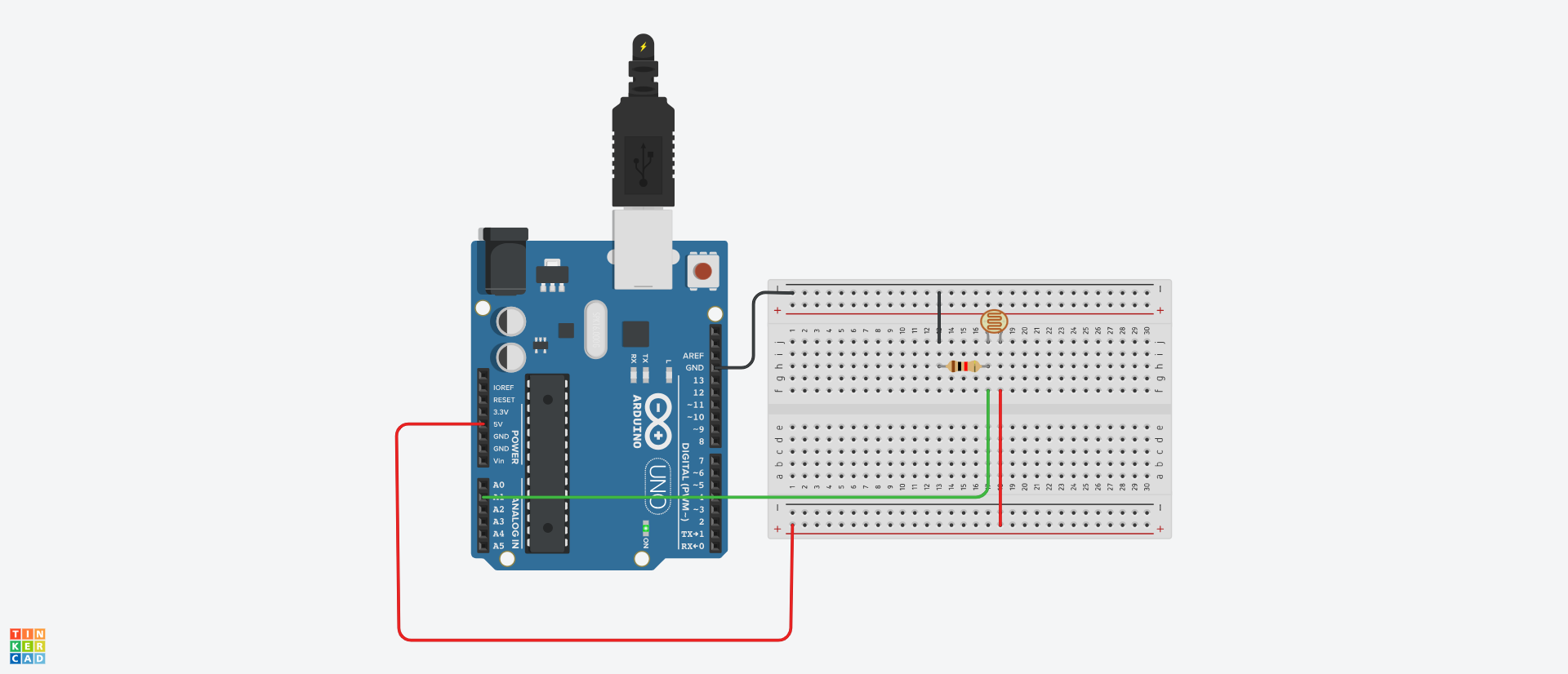 Configuration diagram
In the circuit above, one leg of the LDR is connected to 5V (volts). The other leg is connected to a 1K Ohm resistor — one end of the resistor is connected to ground (GND) while the other end is connected to an analog pin (A1 in our circuit).
Here's the code:
int ldrPin = A1;
int ldrValue;

void setup() {
  pinMode(ldrPin, INPUT);
  Serial.begin(9600);
}

void loop() {
  ldrValue = analogRead(ldrPin);
  Serial.println(ldrValue);
  delay(1000);
}
In the code above, we created a variable called ldrpin with a value of A1. This denotes the connection made in the circuit where one leg of the LDR is connected to the analog pin. This pin will help us know the value of the sensor.
We then created an ldrValue variable which will be used to store the value of the sensor.
In the setup() function, we set the LDR as an INPUT pin. We also initialized the serial monitor.
Next, we read the value of the LDR using the analogRead function, and stored the value in the ldrValue variable:
ldrValue = analogRead(ldrPin);
Lastly, we printed the read value to the serial monitor with a delay of 1000 milliseconds (one second).
At this point, if you increase the exposure of light on the LDR, the value increases. If you decrease the light intensity or cover the sensor to block off light, the value will decrease or become zero, respectively.
How to Use the Ultrasonic Sensor in Arduino
The ultrasonic sensor is generally used to measure the distance of objects. You can use this sensor in a lot of applications like:
- Home automation (you can perform certain actions when the presence of an object/human is sensed, like turning on lights in a dark room).
- Automated doors.
- Security systems.
- Measurement of distance, and so on.
Just like other sensors, there are various types. In this example, we'll use the HC-SR04 ultrasonic sensor. Don't worry, the working principle is the same. So if you understand how to use this one, you can configure and use other types of ultrasonic sensors you come across.
Here's what the circuit diagram looks like:
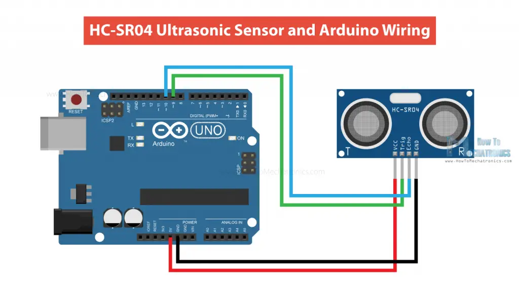 Configuration diagram (from https://howtomechatronics.com/tutorials/arduino/ultrasonic-sensor-hc-sr04/)
The sensor has four pins — VCC, Trig, Echo, and GND.
- The VCC pin is connected to 5V on the Uno board
- The Trig pin is connected to digital pin 9.
- The Echo pin is connected to digital pin 10.
- The GND pin is connected to GND on the Uno board.
The trig pin is used to "trigger" the ultrasonic sensor while the echo pin is used to distance of objects based on the amount of time it takes for ultrasonic waves/signals to bounce back from an object.
Here's a code example:
int trigPin = 9;
int echoPin = 10;

long duration, distance;

void setup() {
  Serial.begin(9600);
  pinMode(trigPin, OUTPUT);
  pinMode(echoPin, INPUT);
}

void loop() {
  digitalWrite(trigPin, HIGH);
  delayMicroseconds(10);
  digitalWrite(trigPin, LOW);

  duration = pulseIn(echoPin, HIGH);

  distance = (duration / 2) * 0.0343;

  Serial.print("Distance: ");
  Serial.print(distance);
  Serial.println(" cm");

  delay(1000);
}
In the code above, the trig pin denotes digital pin 9, and the echo pin denotes digital pin 10.
We declared two variables — duration and distance — to be used to store their respective values.
We triggered the sensor by sending the HIGH signal to the trigger pin for 10 microseconds. Without this, the sensor might not work:
  digitalWrite(trigPin, HIGH);
  delayMicroseconds(10);
  digitalWrite(trigPin, LOW);
We measured and stored the duration of the ultrasonic pulse/signals using the pulseIn(echoPin, HIGH) function and stored it in the duration variable.
We then calculated the duration in centimeters and stored it in the distance variable.
Lastly, we printed the distance to the serial monitor with a delay of 1000 milliseconds.
At this point, you can place an object closer to or farther away from the sensor and see the value of the distance of the object change in the serial monitor.
What are Actuators in Arduino?
Actuators in Arduino are components that convert electrical signals into physical/mechanical motion.
Here are some actuators:
- LED (Light Emitting Diode): Used as light/visual indicators.
- Buzzer: Used to produce sound.
- Relay modules: Used to control high voltage devices.
- LCD (Liquid Crystal Display): Used as visual display for text, images, sensor data, and so on. We'll dedicate a separate chapter to displays.
- Servo motors: Used to control angular or rotational motion (an example is the movement of a robotic arm).
We'll focus on the buzzer and LED in this section.
How to use LEDs in Arduino
LEDs are usually the first components you learn about in Arduino. There are easy to connect and use.
Here's what an LED looks like:

Here's the circuit connection:
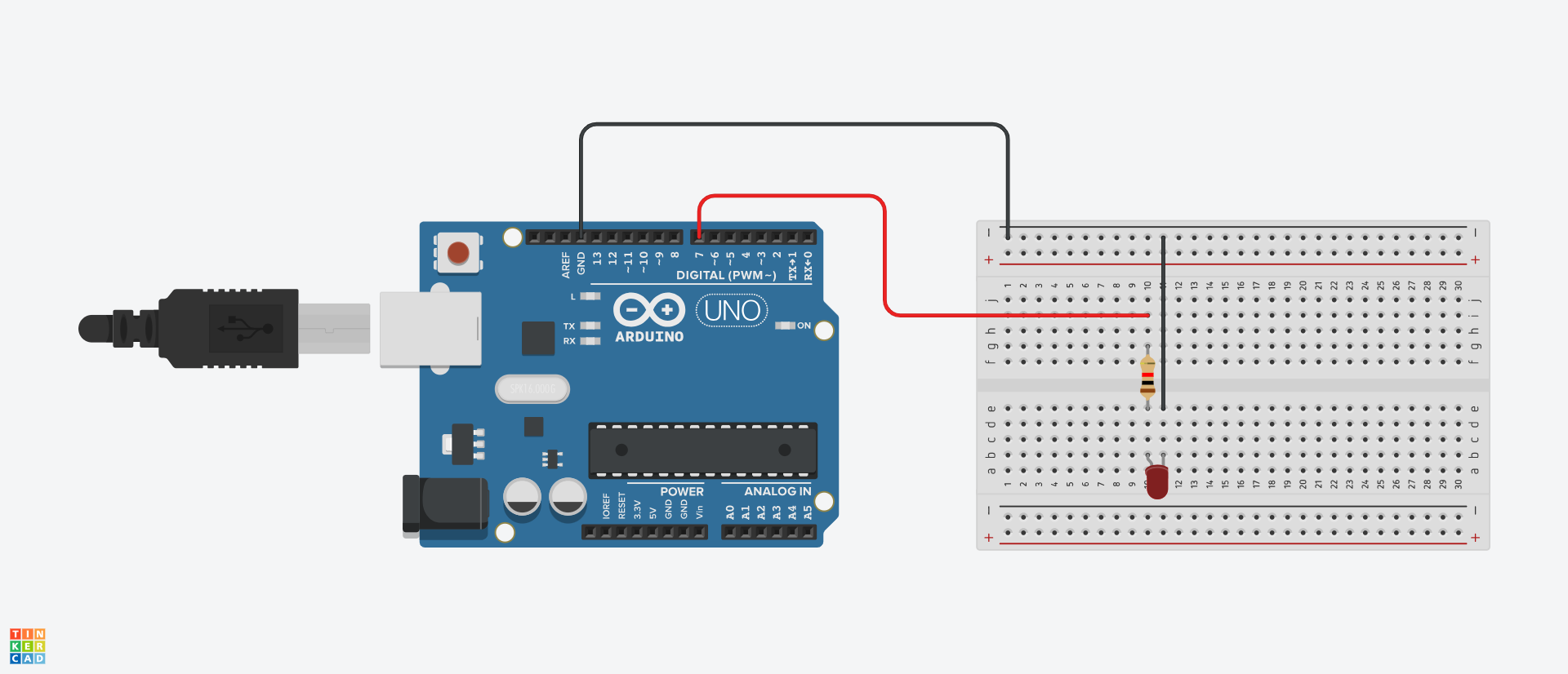
In the circuit above, the longer leg of the LED (the anode or positive leg) is connected to digital pin 7.
The shorter leg (cathode) is connected to ground.
Here's the code:
int redLED = 7;

void setup() {
  pinMode(redLED, OUTPUT);
}

void loop() {
  digitalWrite(redLED, HIGH);
  delay(1000);
  digitalWrite(redLED, LOW);
  delay(1000);
}
The code above will make the LED blink once the code has been uploaded.
How to use a Buzzer in Arduino
You can use buzzers to produce sound. There are generally two types of buzzers: active and passive buzzers.
Active buzzers usually have a predefined type of sound that they produce when voltage is supplied to them. The sound cannot be modified. Active buzzers have an internal circuit that triggers the sound production.
Passive buzzers are a bit more flexible when it comes to producing sound because they rely on external signals. This means that you can determine the frequency (or frequencies) of the sound produced by the buzzer.
Buzzers can be used in different applications like:
- Alarm systems.
- Sound indictor for home appliances.
- Doorbells.
- Communication devices to denote the start/end of a signal communication, and so on.
We'll work with the passive buzzer because of its flexibility. This is what it looks like:
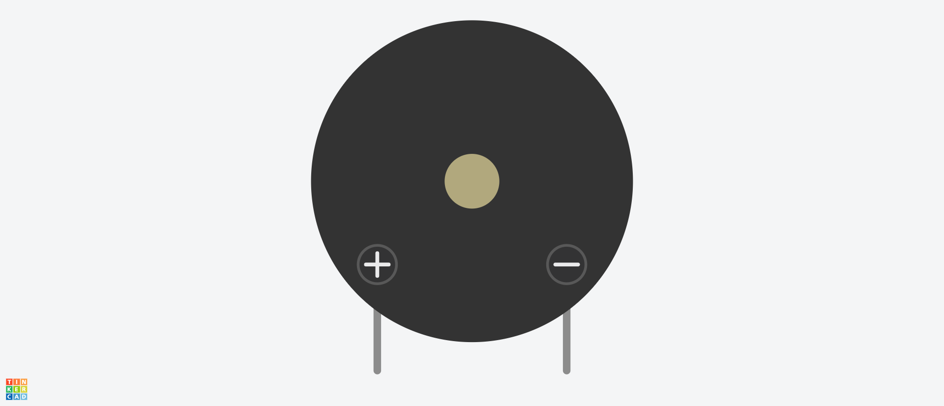
The buzzer has a positive and negative terminal. The positive is connected to a digital pin while the negative is connected to ground.
Here's the circuit diagram:
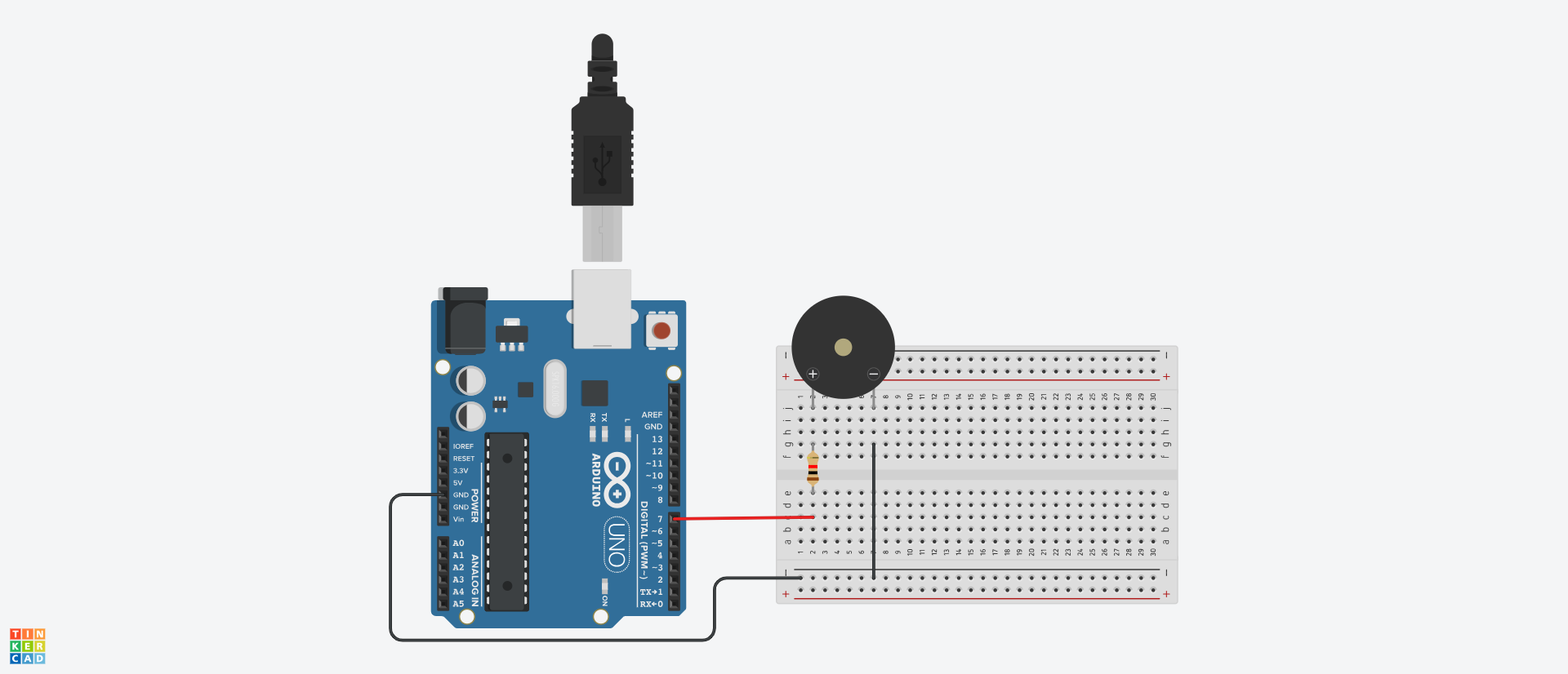
In this example, we'll use the buzzer to produce the DO, RE, MI, FA, SOL, LA, TI music notes sound.
Here's the code:
int buzzerPin = 7;

int notes[] = {262, 294, 330, 349, 392, 440, 494};

int noteDurations[] = {400, 400, 400, 400, 400, 400, 400};

void setup() {
  pinMode(buzzerPin, OUTPUT);
}

void loop() {
  for (int i = 0; i < 8; i++) {
    tone(buzzerPin, notes[i], noteDurations[i]);
    delay(noteDurations[i] + 50);
    noTone(buzzerPin);
  }

  delay(1000);
}
In the code above, we used the buzzerPin variable to denote pin 7 on the Uno board.
We then created an array called notes[] which stores the respective frequency of each note, and another array called noteDurations which stores the duration of each note as they're being produced by the buzzer.
In the void loop() function, we looped through each note a played them using the tone() function. The function takes in three parameters — the pin connected to the buzzer, the frequency, and the duration.
We used the noTone() function to stop the generation of sound. Lastly, we added a delay of 1000 milliseconds which is the amount of time it'll take to play the notes from the start after the last note has been played.
If you've followed along up to this point, then you should have the DO, RE, MI, FA, SOL, LA, TI music notes playing through the buzzer.
Arduino Sensor and Actuator Example
Now that you understand what sensors and actuators are and how to use them, let's use them together in one project.
In many embedded systems, sensors and actuators work together to get a specific task/functionality done. Here's how that works:
- A sensor detects/senses changes in the environment, and sends signals to the microcontroller to notify it of the detected changes.
- The microcontroller processes the signals from the sensor. Depending on the existing logic (defined in the code), it sends signals to the actuator.
- The actuator converts the signal from the microcontroller to physical/mechanical motion.
Let's demonstrate these using an example. The idea here is to turn on an LED in a dark environment and turn it off when there's enough light.
The sensor will be the LDR sensor, the microcontroller will be the Arduino Uno board/software, and the actuator will be the LED.
Here's the circuit diagram:
Here's the code:
int redLED = 7;

int ldrPin = A1;
int ldrValue;

void setup() {
  pinMode(ldrPin, INPUT);
  pinMode(redLED, OUTPUT);
  Serial.begin(9600);
}

void loop() {
  ldrValue = analogRead(ldrPin);

  if (ldrValue > 200) {
    digitalWrite(redLED, LOW);
  } else if (ldrValue < 200) {
    digitalWrite(redLED, HIGH);
  }

  Serial.println(ldrValue);
  delay(1000);
}
As usual, we created variables to represent the Arduino pins connected to the LED and LDR. We then set the LDR as INPUT and the LED as output in the setup() function.
We read the value of the LDR using the analogRead() function and stored it in the ldrValue variable.
Next, we used the an if statement to check the value of the LDR.
If the value is greater than 200, we turn off the LED. If the value is less than 200, we turn on the LED.
Chapter 6: How to Use the Serial Monitor in Arduino
The serial monitor is a useful tool for every Arduino builder. You can use it for a variety of tasks like:
- Debugging and testing code/components.
- Serial communication between the Arduino board and the computer.
- Display sensor and component data and readings.
In this chapter, you'll learn how to initialize and use the serial monitor using the Arduino IDE. You'll learn about different built-in functions that can be used to send and receive data between the Arduino board and the computer.
Lastly, you'll build a project that uses values sent from the serial monitor to power specific LEDs connected to the Arduino board.
How to Initialize the Serial Monitor With Serial.begin()
You can use the Serial.begin() function to initialize the serial monitor. It takes in the baud rate as its parameter. Here's what the syntax looks like:
Serial.begin(baudRate)
The baud rate is the speed of data transfer between the Arduino board and the computer or any other device communicating with the Arduino board through the serial monitor.
The most commonly used baud rate is 9600, but you'll also come across resources that make use of 115200, 57600, and 38400, and so on. Whichever baud rate you specify in the Serial.begin() function should always match the baud rate seen in the serial monitor window.
For example, we can initialize the serial monitor in the IDE using the Serial.begin() function like this:
void setup() {
  Serial.begin(9600);

}

void loop() {
  // put your main code here, to run repeatedly:

}
In the code above, using the Serial.begin() function, we initialized the serial monitor in the setup() function with a baud rate of 9600.
At this point, nothing is happening. You can verify that the baud rates match by opening the serial monitor window. Once you have it open, you should have the serial monitor appear at the base of the IDE. You'll see the baud rate of the serial monitor within the window, usually written like "9600 baud".
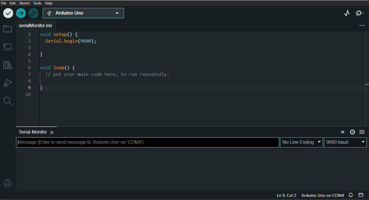 Image showing baud rate
If you're using an older version of the IDE, the serial monitor may pop up as a separate window. The functionality is still the same.
Now that we've initialized the serial monitor, let's see how to send and receive data with it.
How to Send Data with Serial Monitor
You can use different built-in functions reserved for serial communication in Arduino. We won't discuss all the built-in serial functions in Arduino – we'll just look at some you'll use/come across regularly. You can see more functions here.
print() and println() Functions
The print() and println() functions both print data to the serial monitor. The difference between the two is that print() prints data on the same line while println() prints each data on a new line.
Here are some examples:
void setup() {
  Serial.begin(9600);
}

void loop() {
  Serial.print("Hello");
  delay(1000);
}
In the code above, we used the print() function to print "Hello" to the serial monitor repeatedly with a delay of 1000 milliseconds. Here's what the output looks like in the serial monitor:

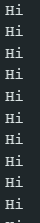
Here's another example using the println() function:
void setup() {
  Serial.begin(9600);
}

void loop() {
  Serial.println("Hi");
  delay(1000);
}
Here's the output in the serial monitor:
How to Receive Data with Serial Monitor
We'll discuss four functions in this section — available(), readString(), parseInt(), and parseFloat(). You can read up on other serial functions here.
available() Function
The Serial.available() function checks the number of characters in the serial port. It is mostly use to run code only when data is available in the serial monitor.
Here's a code example:
int userInput;

void setup(){
  Serial.begin(9600);
}

void loop(){
  if (Serial.available() > 0) {
    userInput = Serial.parseInt();

    Serial.println(userInput);
  }

}
In the code above, the code block in the if statement will not run until the number of characters in the serial monitor is greater than 0.
When you initialize the serial monitor, the number of readable characters will be zero because there is no data available yet. The Serial.available() function checks and returns the number of characters available in the serial monitor. So it is used to create logic that only lets code be executed when data is available.
readString() Function
You can use the readString() function to read characters from the serial monitor. It returns a string object so whatever values/characters you input in the serial monitor will be seen as string values when using the readString() function.
String userInput;

void setup(){
  Serial.begin(9600);
}

void loop(){
  if (Serial.available() > 0) {
    userInput = Serial.readString();

    Serial.println(userInput);
  }

}
parseInt() Function
The parseInt() function returns valid integer values from incoming serial data. Non integer values will be returned as 0.
int userInput;

void setup(){
  Serial.begin(9600);
}

void loop(){
  if (Serial.available() > 0) {
    userInput = Serial.parseInt();

    Serial.println(userInput);
  }

}
parseFloat() Function
The parseFloat() function returns valid floating point numbers from incoming serial data.
float userInput;

void setup(){
  Serial.begin(9600);
}

void loop(){
  if (Serial.available() > 0) {
    userInput = Serial.parseFloat();

    Serial.println(userInput);
  }

}
Serial Monitor Project
In this section, you'll build a project that uses string values from the serial monitor to turn on LEDs. We'll make use of some of the serial functions discussed in previous sections.
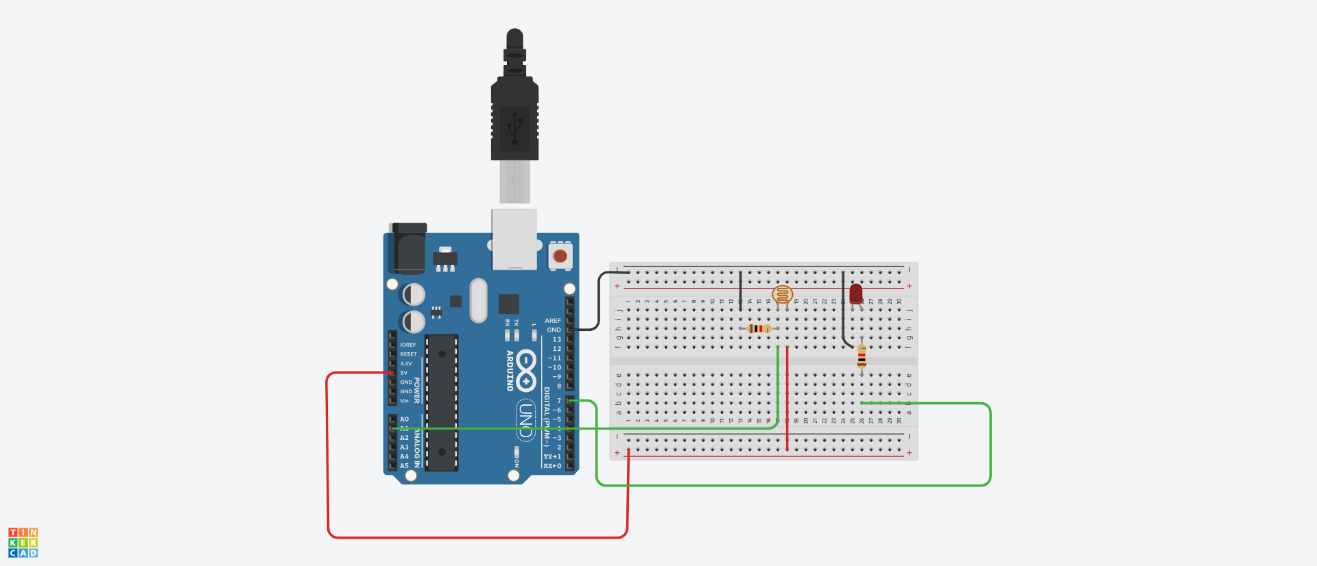
Here's the circuit diagram:
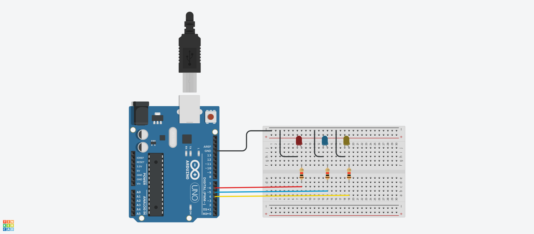
In the circuit diagram above, we have three LEDs. The red LED is connected to pin 6, the blue LED to pin 5, and the yellow LED to pin 4.
Here's the code:
int redLED = 6;
int blueLED = 5;
int yellowLED = 4;
String userInput;
void setup(){
pinMode(redLED, OUTPUT);
pinMode(blueLED, OUTPUT);
pinMode(yellowLED, OUTPUT);
Serial.begin(9600);
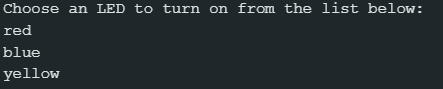
Serial.println("Choose an LED to turn on from the list below:");
Serial.println("red");
Serial.println("blue");
Serial.println("yellow");
}
void loop(){
if (Serial.available() > 0) {
userInput = Serial.readString();
if (userInput == "red") {
digitalWrite(redLED, HIGH);
digitalWrite(blueLED, LOW);
digitalWrite(yellowLED, LOW);
}
if (userInput == "blue") {
digitalWrite(redLED, LOW);
digitalWrite(blueLED, HIGH);
digitalWrite(yellowLED, LOW);
}
if (userInput == "yellow") {
digitalWrite(redLED, LOW);
digitalWrite(blueLED, LOW);
digitalWrite(yellowLED, HIGH);
}
}
}
Let's break down the code above.
Just like the connection in the circuit diagram, we initialized the three LEDs with their respective pin numbers. We also created a string variable called userInput that will be used to store the data from the serial monitor:
int redLED = 6;
int blueLED = 5;
int yellowLED = 4;
We then configured the three LEDs as output pins using the pinMode() function:
pinMode(redLED, OUTPUT);
pinMode(blueLED, OUTPUT);
pinMode(yellowLED, OUTPUT);
We initialized the serial monitor with a baud rate of 9600, and printed some strings to give users a hint at the expected values to be used in the serial monitor:
Serial.begin(9600);

Serial.println("Choose an LED to turn on from the list below:");
Serial.println("red");
Serial.println("blue");
Serial.println("yellow");
At this point, you'll have an output like this in the serial monitor:
Using the Serial.available() function, we check for availability of serial data before running the code in the if statement:
if (Serial.available() > 0) {
    ...
}
The next thing we did was to read and return the incoming data as string values, and store the data in the userInput variable. We did that using the readString() function:
userInput = Serial.readString();
Lastly, we used if statements to check which LED color value the user has typed in/sent through the serial monitor, then turn on/off the respective LEDs:
if (userInput == "red") {
  digitalWrite(redLED, HIGH);
  digitalWrite(blueLED, LOW);
  digitalWrite(yellowLED, LOW);
}

if (userInput == "blue") {
  digitalWrite(redLED, LOW);
  digitalWrite(blueLED, HIGH);
  digitalWrite(yellowLED, LOW);
}

if (userInput == "yellow") {
  digitalWrite(redLED, LOW);
  digitalWrite(blueLED, LOW);
  digitalWrite(yellowLED, HIGH);
}
If you type and send red through the serial monitor, the red LED comes on while the others goes off. The same logic applies to sending blue or yellow through the serial monitor.
Chapter 7: How to Use Displays in Arduino
You can use display components in Arduino to represent data visually in different formats like text, images, and so on.
Displays provide an alternative to showing data other than the serial monitor. You can use them to display sensor values, instructions to users, user input, and so on.
There are various types of display components when it comes to building with Arduino but we'll focus on the LCD (Liquid Crystal Display).
To be more specific, we'll use the 16 x 2 LCD (HD44780). This is what it looks like:
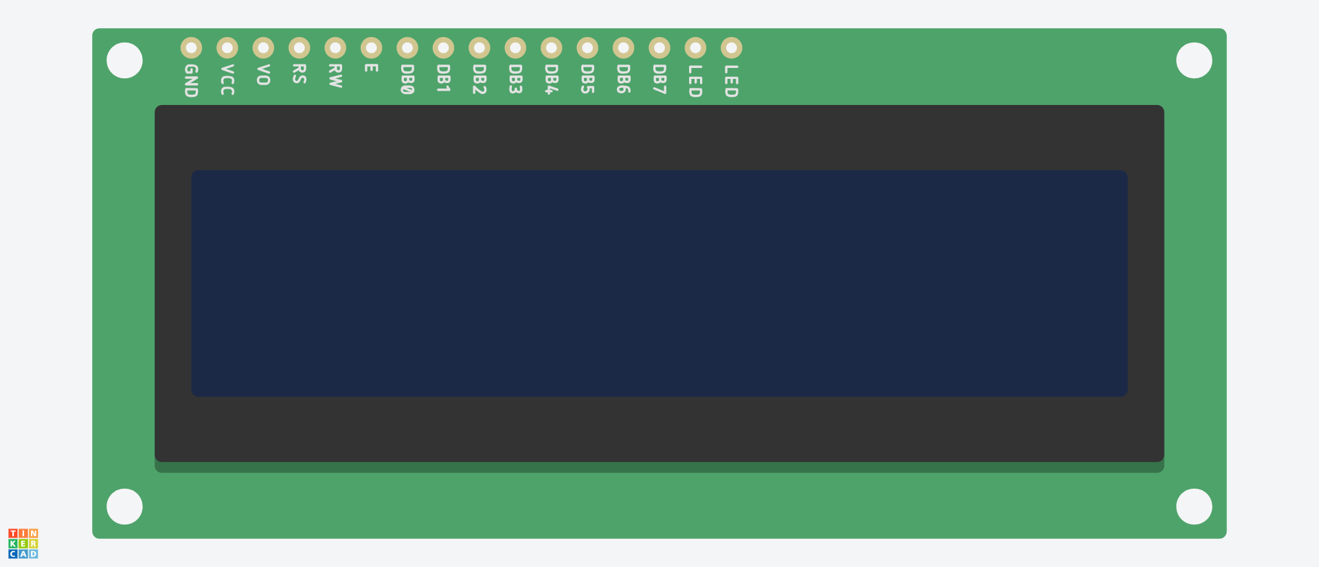
From the image above, there are sixteen pins with different values. We'll use most of these pins to make connections to the Uno board which will enable us use and control the component.
There are generally two ways of connecting the LCD — using the built-in library or using a third-party library.
With the built-in LiquidCrystal library, you'll make use of about 12 pins on the LCD component. When it comes to using a third-party library like LiquidCrystal_I2C, you'll make use of just 2 pins.
We'll be using the first method — this will help you understand how the pins work. Now let's talk about those pins.
What are the pins in an LCD used for?
The pins control functionalities like memory management, data transfer, and power on an LCD. Let's talk about them in detail:
- The first pin from the left is the GND pin, which is the LCD's ground pin. It is connected to GND on the Arduino board. In some LCD modules, it may be written as VSS.
- The VCC is the power pin which is connected to 5V on the Arduino board. In some LCD modules, it may be written as VDD.
- The V0 pin is used to adjust the contrast of the LCD. It is connected to a potentiometer. Tuning the potentiometer changes the contrast of the data being displayed.
- The RS (Register Select) pin can be used to control the LCD's memory. It is usually connected to a digital pin.
- The RW (Read/Write) pin controls whether data is written or read to the LCD. It is usually connected to ground (GND) which sets the LCD to write mode — this enables you to send and display data with the LCD.
- The E (Enable) pin "enables" data transfer between the microcontroller (in our case, the Uno board) and the LCD. It is usually connected to a digital pin.
- The D0 to D7 (can also be written as DB0 to DB7) are the data pins. There are used to send data to the LCD in bits. In most cases, the D4 to D7 pins are used. The main difference is that data is sent in 4-bits with the D0 to D3 pins, while data is sent in 8-bits with the D4 to D7 pins. There are usually connected to digital pins.
- The LED pins are used to control the backlight of the LCD. In some LCD modules, they may be written as BLA and BLK, or A and K. The first LED pin is connected to 5V using a resistor while the second LED pin is connected to ground (GND).
Example #1 – How to Connect and Use an LCD with Arduino
In the last section, we talked about the meaning of the pins on an LCD. In this section, you'll see a practical example on how to connect them in a circuit, and write code to display data on the LCD.
We'll use the following components:
- Arduino Uno.
- 16 x 2 LCD.
- Potentiometer.
- Jumper wires.
- Resistors.
- Breadboard.
Here's what the circuit diagram looks like:

In the circuit above, we made the following connections from the LCD to the Uno board:
- The LCD's GND pin was connected to GND on the Uno board.
- The LCD's VCC pin was connected to 5V on the Uno board.
- The V0 pin was connected to the potentiometer.
- The RS pin was connected to digital pin 4 on the Uno board.
- The RW pin was connected to GND on the Uno board.
- The LCD's D4 was connected to digital pin 6 on the Uno board.
- The LCD's D5 was connected to digital pin 7 on the Uno board.
- The LCD's D6 was connected to digital pin 8 on the Uno board.
- The LCD's D7 was connected to digital pin 9 on the Uno board.
- The first LED pin was connected to 5V.
- The second LED pin was connected to GND.
For the potentiometer, one of the outer legs (either the left or right) was connected to 5V, the other outer leg was connected to GND. Then the middle leg of the potentiometer was connected to the V0 pin on the LCD. This will enable you to control the contrast of the LCD.
Next, we'll write some code!
#include <LiquidCrystal.h>

LiquidCrystal lcd(4, 5, 6, 7, 8, 9);

void setup() {
  lcd.begin(16, 2);
  lcd.print("freeCodeCamp!");
}

void loop() {

}
In the code above, we first included/imported the built-in LiquidCrystal library which can be used to interact with an LCD using Arduino code: #include <LiquidCrystal.h>.
We then initialized the lcd object with the required pin numbers: LiquidCrystal lcd(4, 5, 6, 7, 8, 9). The first number denotes the RS pin. The second number denotes the E pin. The last four numbers denote the data pins (D4 to D7).
Next, we initialized the number of columns and rows using the lcd.begin() function: lcd.begin(16, 2). We have 16 columns and 2 rows.
The lcd.print function prints data to the LCD. If you've made all the connections right, you should see "freeCodeCamp" displayed on the LCD.
In the next examples, we'll work with user input and sensor data, and also see other lcd functions.
Example #2 – How to Display User Input with LCD in Arduino
In this example, we'll accept input from the user using the serial monitor, and display the input along with a welcome message on the LCD screen.
We'll make use of the same circuit in the previous example. Here's the code:
#include <LiquidCrystal.h>
LiquidCrystal lcd(4, 5, 6, 7, 8, 9);

String userInput;

void setup() {
  Serial.begin(9600);
  lcd.begin(16, 2);

  lcd.print("Input name");

  lcd.setCursor(0, 1);
}

void loop() {
  if (Serial.available() > 0) {

    userInput = Serial.readString();
    lcd.print("Welcome " + userInput);
  }
}
In the code above, we created a string variable called userInput which will be used to store the value of the user's input.
We then initialized the serial monitor — Serial.begin(9600);
Next, we set the rows and columns of the LCD using the lcd.begin function.
Using the lcd.print function, we printed "Input name" on the LCD screen.
This was followed by the lcd.setCursor(0, 1) function which has two parameters — 0 and 1. 0 represents first column on the left while 1 represents the second row. So the cursor will be set to the second line of the LCD.
We set the cursor to be on the second line because we already have some text ("input name") on the first line so it would be more ideal in this case to print the message to the user on the next line. I'll show you an alternative way to do this after this example.
In the void loop() function, we used the Serial.readString() function to read the value of user's input and stored it in the userInput variable.
Lastly, we printed a welcome message and the user's name in the LCD. This will be printed on the second line because that's where we set the cursor to be.
Play around with the code and see what happens as you adjust the parameters of the lcd.setCursor() function. This will help you understand it better.
Example #2 Alternative
An alternative way to print the message to the user is by using the same line where the initial message was displayed. We can clear whatever is written on the first row of the LCD and display a different value.
Here's how:
#include <LiquidCrystal.h>
LiquidCrystal lcd(4, 5, 6, 7, 8, 9);

String userInput;

void setup() {
  Serial.begin(9600);
  lcd.begin(16, 2);

  lcd.print("Input name");
}

void loop() {
  if (Serial.available() > 0) {
    lcd.clear();
    userInput = Serial.readString();
    lcd.print("Welcome " + userInput);
  }
}
In this example, we used the lcd.clear() function to clear the initial request message and display/print the welcome message to the user. The rest of the logic is the same.
So when you type in a name in the serial monitor an hit enter, the request message ("Input name") will be cleared while the welcome message will be displayed with the name you inputted.
Example #3 – How to Display Sensor Data with LCD in Arduino
In this example, we'll display data from a sensor on the LCD. We'll use the temperature sensor. The logic here is to sense the temperature of a room and display the varying values on the LCD.
Here are the components we'll use:
- Arduino Uno.
- 16 x 2 LCD.
- Light-Dependent Resistor (LDR).
- Potentiometer.
- Jumper wires.
- Resistors.
- Breadboard.
Here's the circuit diagram:
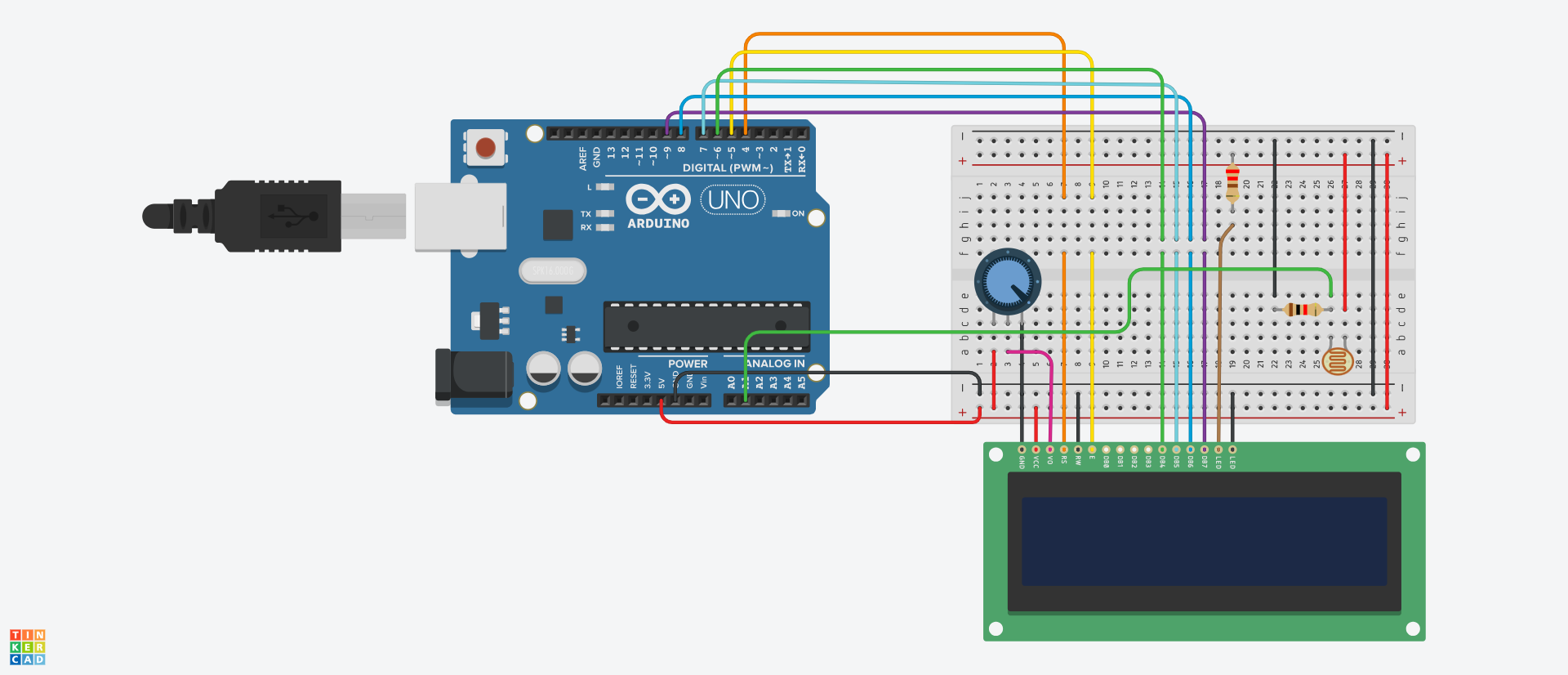
The circuit diagram is almost the same as the ones in the previous examples, except that we added an LDR to measure the intensity of light. Using the LDR, we'll read, store, and display the value of light intensity on the LCD.
Here's the code:
#include <LiquidCrystal.h>
LiquidCrystal lcd(4, 5, 6, 7, 8, 9);

int ldrPin = A1;
int ldrValue;

void setup() {
  pinMode(ldrPin, INPUT);
  lcd.begin(16, 2);
}

void loop() {
  ldrValue = analogRead(ldrPin);

  lcd.clear();
  lcd.setCursor(0, 0);
  lcd.print("LDR value:");

  lcd.setCursor(0, 1);
  lcd.print(ldrValue);

  delay(1000);
}
Let's break down the code.
We started by including the built-in LiquidCrystal library and initialized the respective pins for working with the LCD (refer to the first example if you do not understand how the connection and initialization works).
We then created two variables: ldrPin which denoted the analog pin connected to the LDR, and ldrValue to store the readings from the LDR.
In void setup(), we configured the LDR as an input pin and set the columns and rows of the LCD.
Next, we read the value of the LDR using the analogRead function and stored that value in the ldrValue variable.
Using the lcd.clear() function, we clear the display after each reading. This helps in making the reading appear more accurately. If you remove the function, then some values will still be on display and make your results appear inaccurately (I spent about thirty minutes figuring this out 😂).
After that, we set the cursor on the first row and column of the LCD: lcd.setCursor(0, 0), and displayed a message ("LDR value:").
Using the lcd.setCursor(0, 1) function, we moved the cursor down to the second row, and used lcd.print(ldrValue) to print/display the value of the LDR on the LCD.
Lastly, we added a delay of 1000 milliseconds.
Now you can see the value of light intensity in your environment displayed on the LCD.
You can use a flashlight to increase and decrease the exposure of light on the LDR, and then observe the values change on the LCD. Pretty cool!
Conclusion
Congratulations! We've come to the end of this handbook. You now have enough knowledge to take on bigger projects.
And that should be your next goal — applying these concepts to projects that aid you and the people around you. There is no limit to what you can create. You can start by watching a couple of videos to see the type of projects people build, then you can come up with yours.
This handbook covered the necessary parts of Arduino (both hardware and software) that you'll need as a beginner to kickstart your journey.
The best way to improve and retain what you've learned is by practicing and building.
Happy tinkering!